Yamaha EMX5000-20 Owner's Manual - Page 18
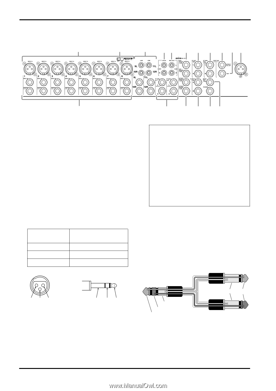
Input/output panel, Channel input jacks INPUT A, INPUT B, EMX5000-20: 1-16, INSERT I/O insert jacks
 |
View all Yamaha EMX5000-20 manuals
Add to My Manuals
Save this manual to your list of manuals |
Page 18 highlights
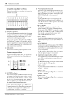
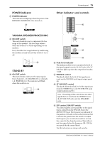
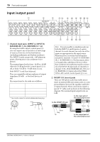
16 Front and rear panel Input/output panel 1 3 4 56 8 0 A E F G 2 1 Channel input jacks (INPUT A, INPUT B) EMX5000-20: 1-16, EMX5000-12: 1-8 By using the GAIN control (control panel 2) you can connect any of the jacks to a wide range of sources, from mics to line-level devices (including synthesizers and rhythm machines). The INPUT A jacks can provide +48V phantom power, allowing you to use condenser microphones. The nominal input level is from -16 dB to -60 dB when the 26 dB pad switch (control panel 1) is off, or from +10 dB to -34 dB when it is on. Both INPUT A and B are balanced. They are compatible with microphones of output impedance 50-600Ω or line level devices of 600Ω. Pin connections for the jacks are as follows: INPUT A jacks (XLR type) INPUT B jacks (TRS phone jacks) * Pin 1: ground Sleeve: ground Pin 2: hot (+) Tip: hot (+) Pin 3: cold (-) RIng: cold (-) * You can also connect a normal unbalanced phone plug. 21 3 S RT + - GND GND - + 7 9 B DC Note: It is not possible to simultaneously use both the INPUT A and B inputs of a given channel. For each channel, use only one of the inputs as appropriate for the input source. Phantom power is switched on/off simultaneously for channels 1-8 and 9-16 (EMX500020), 1-8 (EMX5000-12). For this reason, devices (in particular, unbalanced devices) other than condenser microphones must be connected to the INPUT B input jacks of channels or channel 17/18-19/20 (EMX5000-20), 9/10-11/ 12 (EMX5000-12) input jacks if the PHANTOM +48V switch (control panel 3) is on. 2 INSERT I/O (insert) jacks These are TRS phone jacks that enable you to insert an external effect processor, such as a compressor/limiter, between the equalizer and fader of input channels. These connections require a special "Y" cable, such as shown in the following diagram. The nominal input/output levels are 0 dB. to the input jack of the external processor to the INSERT I/O jack Sleeve Tip Sleeve Ring Tip to the output jack of the external processor EMX5000-20/EMX5000-12-Owner's Manual
-
 1
1 -
2
-
3
-
4
-
5
-
6
-
7
-
8
-
9
-
10
-
11
-
12
-
 13
13 -
 14
14 -
 15
15 -
 16
16 -
 17
17 -
 18
18 -
 19
19 -
 20
20 -
 21
21 -
 22
22 -
 23
23 -
24
-
25
-
26
-
27
-
28
-
29
-
30
-
31
-
32
-
33
-
34
-
35
-
36
-
37
-
38
 |
 |