Yamaha EMX5000-20 Owner's Manual - Page 13
Stereo sub input AUX1, AUX2 controls / POST switches - / 12 manual
 |
View all Yamaha EMX5000-20 manuals
Add to My Manuals
Save this manual to your list of manuals |
Page 13 highlights
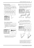
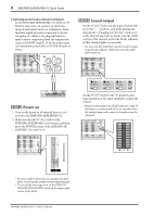
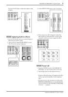
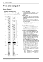
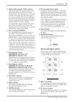
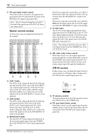
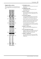
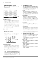
Control panel 11 5 AUX1, AUX2 controls / POST switches These knobs adjust the level at which the input signal will be sent to the AUX1 and 2 buses. Nominal level is when the knob is set to the "√" position. The position from which the signal is sent can be set by the POST switch to either prefader (before the channel fader C) or post-fader (after the channel fader C). When the switch is pressed inward, post-fader is selected. The signal will be output from the AUX1 and 2 buses to the AUX SEND 1 and 2 jacks of the input/output section, and can be sent to external monitor amps or powered speakers. 6 EFF 1, 2 controls (EFFECT) For each channel, these control the amount of signal that is sent to the EFFECT 1, 2 buses. The signal of the EFFECT 1, 2 buses is sent to the EFFECT SEND 1, 2 jack (input/output panel 9). It is also sent to the built-in effect when the ON switch S in the digital effect section is turned on. Note: The amount of signal that is sent to the EFFECT 1, 2 bus from each channel will be affected not only by the setting of the EFFECT 1, 2 control, but also by the setting of the channel fader C (post-fader send). 7 PAN (panpot) control (EMX5000-20: Channels 1-16, EMX5000-12: Channels 1-8) The PAN knobs set the stereo position of the signal that is sent to the STEREO bus. The signal is located in the center when the knob is positioned at "w," at right at R, and at left at L. 8 BAL (balance) control (EMX5000-20: Channels 17/18-19/20, EMX5000-12: Channels 9/10-11/12) The BAL knobs set the balance between the left and right channels, and assign the signals received at inputs 17/18-19/20, 9/10-11/12 to the STEREO bus. 9 ON switch, indicator This is an on/off switch for the input signal of each channel. The indicator will light if this switch is turned on. 0 PEAK indicator The indicator will light 3 dB before clipping, warning that clipping level is near. A SIGNAL indicator This indicator will light if a signal is being input to the corresponding channel. B PFL (pre-fader listen) switch Channels for which this switch is on will send a signal from a post-EQ pre-fader location to the PHONES jack (input/output panel D). Use this when you wish to use the headphones to monitor only a specific channel. Note: If this switch is turned on, you can monitor a channel even if the channel fader is lowered, or if the ON switch is off. This will not affect the signals that are sent to the STEREO bus, AUX 1 and 2 buses, and EFFECT bus. C Channel fader This controls the output level of the input channel signal. D PHANTOM indicator This will light when the PHANTOM switch (input/output panel 3) is on. D s Stereo sub input section In this section, you can adjust the input level of external equipment connected to the ST SUB IN 1, 2 jacks on the input/output panel. E E F F G G E AUX 1, 2 controls This knob adjusts the amount of the signal sent from the ST SUB IN 1 and 2 jacks (input/output panel 7) to the AUX 1, 2 buses. F ST (stereo) control The ST knob adjusts the amount of stereo signal sent from the ST SUB IN 1 and 2 jacks to the STEREO bus. EMX5000-20/EMX5000-12-Owner's Manual
-
 1
1 -
2
-
3
-
4
-
5
-
6
-
7
-
 8
8 -
 9
9 -
 10
10 -
 11
11 -
 12
12 -
 13
13 -
 14
14 -
 15
15 -
 16
16 -
 17
17 -
 18
18 -
19
-
20
-
21
-
22
-
23
-
24
-
25
-
26
-
27
-
28
-
29
-
30
-
31
-
32
-
33
-
34
-
35
-
36
-
37
-
38
 |
 |