Yamaha EMX5000-20 Owner's Manual - Page 17
POWER indicator, YAMAHA SPEAKER PROCESSING, STAND-BY, Other indicators and controls, ON/OFF switch
 |
View all Yamaha EMX5000-20 manuals
Add to My Manuals
Save this manual to your list of manuals |
Page 17 highlights
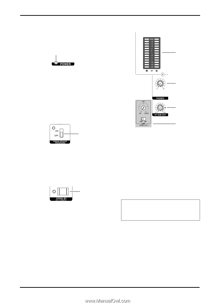
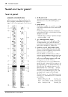
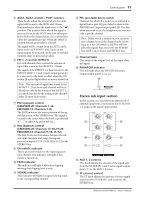
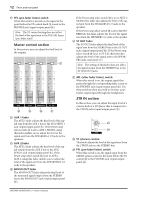
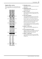
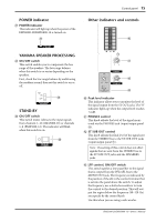
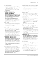
Control panel 15 s POWER indicator [ POWER indicator This indicator will light up when the power of the EMX5000-20/EMX5000-12 is turned on. [ s Other indicators and controls ` s YAMAHA SPEAKER PROCESSING \ ON/OFF switch This switch enables you to compensate the low range of the speakers. The low range balance when this switch is on varies depending on the speakers. First, check the low range balance by auditioning the resultant sound, then set this switch to on or off. \ s STAND-BY ] ON/OFF switch This switch mutes (silences) the input signals from channels 1-16 (EMX5000-20) or channels 1-8 (EMX5000-12). The indicator will blink when this switch is on. ] a b c ^ Peak level indicator This indicator allows you to monitor the level of the signal output from the ST OUT jacks. The "0" indicator lights up when the output level reaches +4 dB. a PHONES control This knob adjusts the level of the signal monitored via the PHONES jack (input/output panel D). b ST SUB OUT control This knob adjusts the final level of the signal sent from the STEREO bus to the ST SUB OUT jacks (input/output panel A). Note: The setting of this control does not affect signals that are sent from the STEREO bus to the ST SUB OUT jacks and the SPEAKERS jacks. c LPF control, ON/OFF switch This switch applies a low-pass filter to the signal that is output from the PFL/AFL bus to the MONO OUT jack. The frequency is indicated by the position of the slit in the control trimmer that is set into the panel above the switch. To adjust the frequency, use a slotted screwdriver to turn the control to the desired position. This will output the region below the frequency (80-120 Hz) you specify by the control knob. Use this when you are using a sub-woofer. EMX5000-20/EMX5000-12-Owner's Manual
-
 1
1 -
2
-
3
-
4
-
5
-
6
-
7
-
8
-
9
-
10
-
11
-
 12
12 -
 13
13 -
 14
14 -
 15
15 -
 16
16 -
 17
17 -
 18
18 -
 19
19 -
 20
20 -
 21
21 -
 22
22 -
23
-
24
-
25
-
26
-
27
-
28
-
29
-
30
-
31
-
32
-
33
-
34
-
35
-
36
-
37
-
38
 |
 |