Yamaha HTR 6230 Owner's Manual - Page 19
Using the VIDEO AUX jacks on the front panel, Connecting the FM and AM antennas - remote
 |
UPC - 027108933054
View all Yamaha HTR 6230 manuals
Add to My Manuals
Save this manual to your list of manuals |
Page 19 highlights
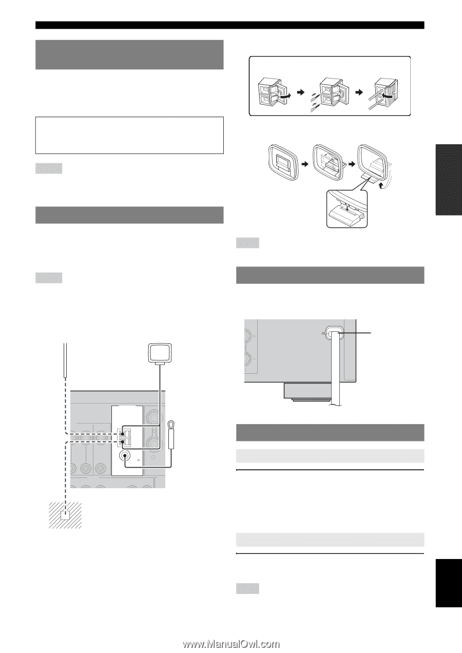
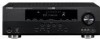
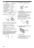
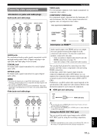
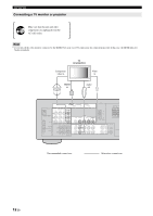
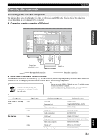
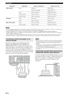
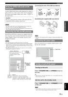
INTRODUCTION PREPARATION Using the VIDEO AUX jacks on the front panel Use the VIDEO AUX jacks on the front panel to connect a game console or a video camera to this unit. To reproduce the source signals input at these jacks, select "V-AUX" as the input source. Caution Be sure to turn down the volume of this unit and other components before making connections. Connections Connecting the wire of the AM loop antenna Open the lever Insert Close the lever Assembling the supplied AM loop antenna Notes • The audio signals input at the DOCK terminal on the rear panel take priority over the ones input at the VIDEO AUX jacks. • The audio signals input at the PORTABLE mini jack take priority over the ones input at the AUDIO L/R jacks. Connecting the FM and AM antennas Both FM and AM indoor antennas are supplied with this unit. In general, these antennas should provide sufficient signal strength. Connect each antenna correctly to the designated terminals. Notes • The AM loop antenna should be placed away from this unit. • A properly installed outdoor antenna provides clearer reception than an indoor one. If you experience poor reception quality, install an outdoor antenna. Consult the nearest authorized Yamaha dealer or service center about outdoor antennas. • The AM loop antenna should always be connected, even if an outdoor AM antenna is connected to this unit. Outdoor AM antenna Use a 5 to 10 m (16 to 32 ft) of vinyl-covered wire extended outdoors from a window. AM loop antenna (supplied) Note • The types of the supplied AM loop antenna is different depending on the models. Connecting the power cable Once all connections are complete, plug the power cable into the AC wall outlet. Power cable L BASIC OPERATION ADVANCED OPERATION ADDITIONAL INFORMATION APPENDIX ANTENNA DEO N DVR OUT MONITOR OUT AM GND Indoor FM antenna (supplied) FM 75 UNBAL. R SURRO AUDIO N DVR OUT CD IN MD/ OUT (PLAY) CD-R (REC) OUTP S Ground For maximum safety and minimum interference, connect the antenna GND terminal to a good earth ground. A good earth ground is a metal stake driven into moist earth. To the AC wall outlet Turning on and off the power Turning on this unit Press ASTANDBY/ON (or dPOWER) to turn on this unit. y • When you turn on this unit, there will be a 4 to 5-second delay before this unit can reproduce sound. Set this unit to the standby mode Press ASTANDBY/ON (or cSTANDBY) to turn off this unit. Note • In the standby mode, this unit consumes a small amount of power in order to receive infrared signals from the remote control. 15 En English
-
 1
1 -
2
-
3
-
4
-
5
-
6
-
7
-
8
-
9
-
10
-
11
-
12
-
13
-
 14
14 -
 15
15 -
 16
16 -
 17
17 -
 18
18 -
 19
19 -
 20
20 -
 21
21 -
 22
22 -
 23
23 -
 24
24 -
25
-
26
-
27
-
28
-
29
-
30
-
31
-
32
-
33
-
34
-
35
-
36
-
37
-
38
-
39
-
40
-
41
-
42
-
43
-
44
-
45
-
46
-
47
-
48
-
49
-
50
-
51
-
52
-
53
-
54
-
55
-
56
-
57
-
58
-
59
-
60
-
61
-
62
 |
 |