Yamaha YSP800S Owner's Manual - Page 100
YSP-800 QUICK REFERENCE GUIDE, This unit, DVD player, Subwoofer - ysp 800 subwoofer
 |
UPC - 027108923543
View all Yamaha YSP800S manuals
Add to My Manuals
Save this manual to your list of manuals |
Page 100 highlights
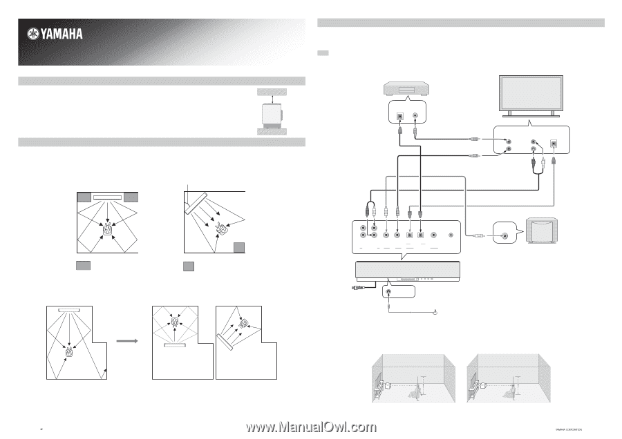
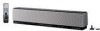
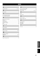
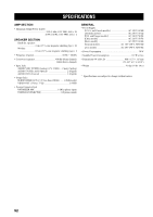
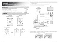
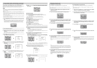
YSP-800 QUICK REFERENCE GUIDE This quick reference guide explains steps to connect a TV and a DVD player to this unit and achieve the surround sound effects in a quick, easy manner. Before installing this unit This unit creates surround sound by reflecting projected sound beams off the walls of your listening room. The surround sound effects produced by this unit may not be sufficient when the unit is installed in the following locations. • Rooms with surfaces inadequate for reflecting sound beams • Rooms with acoustically absorbent surfaces • Rooms with measurements outside the following range W (3 to 7 m) x H (2 to 3.5 m) x D (3 to 7 m) • Rooms with less than 2 m from the listening position to the speaker positions • Rooms where objects such as furniture are likely to obstruct the path of sound beams • Rooms where the listening position is close to the walls • Rooms where the listening position is not in front of this unit Make sure you leave an adequate amount of ventilation space so that heat can escape. Make at least 5 cm of space above or below this unit. Side view Front 5 cm or more Rear 1. Installing this unit Install this unit where there are no obstacles such as furniture obstructing the path of sound beams. Otherwise, the desired surround sound effects may not be achieved. You may install this unit in parallel with the wall or in the corner. Parallel installation Install this unit in the exact center of the wall when it is measured from the left and right corners. Corner installation Install this unit in the corner at a 40º to 50º angle from the adjacent walls. 40° to 50° 2. Connecting external components to this unit Connect this unit to external components such as your TV, DVD player, VCR, digital satellite tuner, cable TV tuner, game console and a subwoofer. ■ Connecting a TV and a DVD player Connect a TV and a DVD player to this unit. If you connect a subwoofer to this unit, you can enjoy reinforced low bass sounds. Note For further information on connecting other components, see pages 14 to 20 in the supplied Owner's Manual. TV DVD player Optical digital output Video output Optical cable (supplied) DVD video pin cable OSD video pin cable (supplied) Video input 1 2 Analog audio output L R Optical digital output Subwoofer pin cable (in case you connect a subwoofer) Audio pin cable (supplied) Optical cable (in case of an optical digital connection) An object, such as furniture Installation example Install this unit so that the sound beams can be reflected off the walls. Wrong An object, such as furniture Correct Correct Monaural input VCR TV/STB SUBWOOFER VIDEO AUDIO INPUT OUT TV/STB AUX OPTICAL DVD COAXIAL DIGITAL INPUT SYSTEM CONNECTOR Rear panel of this unit This unit (U.S.A. and Canada models) Subwoofer To the AC outlet OPTIMIZER MIC Optimizer microphone (supplied) ■ Installing the optimizer microphone The supplied optimizer microphone collects and analyzes the sound that this unit produces in your actual listening environment. Refer to the following two diagrams to install the optimizer microphone in a proper location once it is connected to this unit. If you use a tripod or the supplied cardboard microphone stand to affix the optimizer microphone, try to place the optimizer microphone at the same height as your ears would be when you are seated in your listening position. Using a tripod Using the supplied cardboard microphone stand Optimizer microphone position More than 2 m Within 1 m Within 1 m Tripod Optimizer microphone position More than 2 m Within 1 m Within 1 m Cardboard microphone stand Printed in Malaysia WG29100 © 2005 All rights reserved.
-
 1
1 -
2
-
3
-
4
-
5
-
6
-
7
-
8
-
9
-
10
-
11
-
12
-
13
-
14
-
15
-
16
-
17
-
18
-
19
-
20
-
21
-
22
-
23
-
24
-
25
-
26
-
27
-
28
-
29
-
30
-
31
-
32
-
33
-
34
-
35
-
36
-
37
-
38
-
39
-
40
-
41
-
42
-
43
-
44
-
45
-
46
-
47
-
48
-
49
-
50
-
51
-
52
-
53
-
54
-
55
-
56
-
57
-
58
-
59
-
60
-
61
-
62
-
63
-
64
-
65
-
66
-
67
-
68
-
69
-
70
-
71
-
72
-
73
-
74
-
75
-
76
-
77
-
78
-
79
-
80
-
81
-
82
-
83
-
84
-
85
-
86
-
87
-
88
-
89
-
90
-
91
-
92
-
93
-
94
-
 95
95 -
 96
96 -
 97
97 -
 98
98 -
 99
99 -
 100
100 -
 101
101
 |
 |