Yamaha YSP800S Owner's Manual - Page 31
Installing the optimizer microphone
 |
UPC - 027108923543
View all Yamaha YSP800S manuals
Add to My Manuals
Save this manual to your list of manuals |
Page 31 highlights
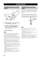
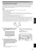
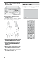
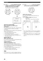
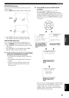
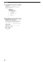
AUTO SETUP Installing the optimizer microphone The supplied optimizer microphone collects and analyzes the sound that this unit produces in your actual listening environment. Follow the procedure below to connect the optimizer microphone to this unit and make sure that the optimizer microphone is placed in a proper location and that there are no large obstacles between the optimizer microphone and the walls in your listening room. Notes • After you have completed the AUTO SETUP procedure, be sure to disconnect the optimizer microphone. • The optimizer microphone is sensitive to heat. - Keep it away from direct sunlight. - Do not place it on top of this unit. • Do not connect the optimizer microphone to an extension cable as doing so may result in an inaccurate sound optimization. • An error may occur during the AUTO SETUP procedure if the optimizer microphone is not properly placed in your listening room. To avoid the possibility of an error: - Do not place the optimizer microphone to the extreme right or left from the center of this unit. - Do not place the optimizer microphone within 2 m from the front of this unit. - Do not place the optimizer microphone more than 1 m from the center height of this unit. • Make sure that there are no obstacles between the optimizer microphone and the walls in your listening room as these objects obstruct the path of sound beams. However, any objects that are in contact with the walls will be regarded as a protruding part of the walls. • The best possible results are achieved if the optimizer microphone is placed at the same height as your ears would be when you are seated in your listening position. However, if this is not possible, you can manually fine-tune the sound beam angle and balance the sound beam output levels using MANUAL SETUP (see page 63) once the AUTO SETUP procedure is completed. • If a subwoofer with adjustable volume and crossover/high cut frequency controls is connected to this unit, set the volume between 9 and 12 o'clock as viewed on a conventional clockface and set the crossover/high cut frequency to the maximum. VOLUME CROSSOVER HIGH CUT MIN MAX MIN MAX Subwoofer 1 Connect the supplied optimizer microphone to the OPTIMIZER MIC jack on the front panel. y You may want to use a tripod or the supplied cardboard microphone stand to affix the optimizer microphone at the same height as your ears would be when you are seated in your listening position. Example of using a tripod SETUP OPTIMIZER MIC 2 Place the optimizer microphone on a flat level surface more than 2 m from the front of the unit and within 1 m from the center height of the unit with the optimizer microphone head upward at your normal listening position. Note Be sure to place the optimizer microphone on an imaginary center line drawn from this unit. Optimizer microphone position More than 2 m (6.5 ft) Within 1 m (3.3 ft) Within 1 m (3.3 ft) Tripod 27 English
-
 1
1 -
2
-
3
-
4
-
5
-
6
-
7
-
8
-
9
-
10
-
11
-
12
-
13
-
14
-
15
-
16
-
17
-
18
-
19
-
20
-
21
-
22
-
23
-
24
-
25
-
 26
26 -
 27
27 -
 28
28 -
 29
29 -
 30
30 -
 31
31 -
 32
32 -
 33
33 -
 34
34 -
 35
35 -
 36
36 -
37
-
38
-
39
-
40
-
41
-
42
-
43
-
44
-
45
-
46
-
47
-
48
-
49
-
50
-
51
-
52
-
53
-
54
-
55
-
56
-
57
-
58
-
59
-
60
-
61
-
62
-
63
-
64
-
65
-
66
-
67
-
68
-
69
-
70
-
71
-
72
-
73
-
74
-
75
-
76
-
77
-
78
-
79
-
80
-
81
-
82
-
83
-
84
-
85
-
86
-
87
-
88
-
89
-
90
-
91
-
92
-
93
-
94
-
95
-
96
-
97
-
98
-
99
-
100
-
101
 |
 |
