Asus M8 M8000 English - Page 60
Modem and LAN Connections optional
 |
View all Asus M8 manuals
Add to My Manuals
Save this manual to your list of manuals |
Page 60 highlights
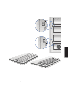
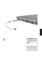
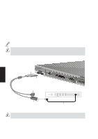
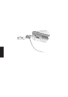
Modem and LAN Connections (optional) The built-in modem and fast-Ethernet model will come with an external cable for connection to RJ-45 Ethernet cabling or to RJ-11 phone cabling. The connector can only be inserted in one orientation and has a triangular icon (or brand name) to represent the top side of the connector. Connect the modem and LAN cable set as shown here. The RJ-11 connector connects to a phone outlet usually in the walls of homes and some commercial buildings (some commercial building may use phone systems with different wiring) via a telephone wire. The RJ-45 connector connects to a hub or switch via an Ethernet cable. NOTE: The built-in modem and fast-Ethernet is a manufacturer's option and cannot be upgraded at a later time. Modem and/or LAN can only be installed later as a PCMCIA card. WARNING! The built-in modem does not support the voltage used in digital phone systems. Do not connect the RJ-11 to digital phone systems or else damage will occur to the Notebook PC. 4. Using A triangle represents the top side Press both sides in to release RJ-11 connector: Connect to wall via common 2- or 4-wire telephone cable HUB 100M Lnk/Act FDX/Col RJ45 Uplink 12345678 1 12345678 2 12345678 3 12345678 4 12345678 5 12345678 6 12345678 7 12345678 8 12345678 RJ45 RJ-45 connector with status LED: Connect to hub or switch via 8wire Ethernet cable Ethernet cable with RJ-45 Connectors WARNING! The modem and/or LAN cable must be removed before transit to prevent damage to the connector. 60
-
 1
1 -
2
-
3
-
4
-
5
-
6
-
7
-
8
-
9
-
10
-
11
-
12
-
13
-
14
-
15
-
16
-
17
-
18
-
19
-
20
-
21
-
22
-
23
-
24
-
25
-
26
-
27
-
28
-
29
-
30
-
31
-
32
-
33
-
34
-
35
-
36
-
37
-
38
-
39
-
40
-
41
-
42
-
43
-
44
-
45
-
46
-
47
-
48
-
49
-
50
-
51
-
52
-
53
-
54
-
 55
55 -
 56
56 -
 57
57 -
 58
58 -
 59
59 -
 60
60 -
 61
61 -
 62
62 -
 63
63 -
 64
64 -
 65
65 -
66
-
67
-
68
-
69
-
70
-
71
-
72
-
73
-
74
-
75
-
76
-
77
-
78
-
79
-
80
-
81
-
82
-
83
-
84
-
85
-
86
-
87
-
88
-
89
-
90
-
91
-
92
-
93
-
94
-
95
-
96
-
97
-
98
-
99
-
100
-
101
-
102
 |
 |
