Asus P I-P55TP4N User Manual - Page 11
Jumpers, Expansion Slots, Connectors
 |
View all Asus P I-P55TP4N manuals
Add to My Manuals
Save this manual to your list of manuals |
Page 11 highlights
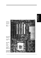
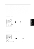
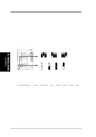
III. INSTALLATION (Map of Board) III. INSTALLATION Jumpers 1) JP4 2) JP5 3) JP16 4) JP22, 23, 24 5) JP26, 27, 28 6) JP14, 15 7) JP7 8) JP13 p. 8 Multi-I/O Selection (Enable/Disable) p. 8 Flash ROM Boot Block Program (Enable/Disable) p. 9 Total Level 2 Cache Size Setting p. 9 Voltage Regulator Output Selection p. 10 CPU External Clock (BUS) Frequency Selection p. 10 CPU:BUS Frequency Ratio p. 11 PS/2 Mouse on IRQ12 (Enable/Disable) p. 11 CMOS RAM (Operation/Clear CMOS Data) Expansion Slots 1) SIMM Slots 2) Cache Expansion 3) CPU ZIF Socket 7 4) ISA Slots 1,2,3 5) PCI Slots 1,2,3 6) PCI 4 / MediaBus p. 12 DRAM Memory Expansion slots p. 14 Socket for Pipelined Burst SRAM Cache Module p. 15 Socket for Central Processing Unit (CPU) p. 16 16-bit ISA Bus Expansion slots p. 16 32-bit PCI Bus Expansion slots p. 18 32-bit PCI Bus Slot and MediaBus Connectors 1) Keyboard p. 19 Keyboard connector (5-pin Female) 2) PS/2 Mouse p. 19 PS/2 Mouse connector (6-pin Block) 3) Parallel Port p. 20 Parallel Port connector (26-pin Block) 4) Serial Port p. 20 Serial Port COM1 & COM2 (10-pin Blocks) 5) Floppy Drive p. 21 Floppy Drive connector (34-pin Block) 6) Power Input p. 21 Motherboard Power connector (12-pin Block) 7) Primary/Second IDE p. 22 Primary/Secondary IDE connector (40-pin Blocks) 8) JP30 (Fan) p. 22 CPU 12V Cooling Fan connector 9) Turbo/Power (CON1) p. 23 Turbo LED/Power LED (2-pins) 10) SMI Switch (CON1) p. 23 SMI Switch lead (2-pins) 11) Reset Switch (CON1) p. 23 Reset Switch lead (2-pins) 12) Key Lock (CON1) p. 23 Keyboard Lock Switch lead (5-pins) 13) Speaker (CON1) p. 23 Speaker connector (4-pins) 14) JP17 (LED) p. 24 IDE LED activity light 16) JP31 (IR) p. 24 Infrared Port Module connector P/I-P55TP4N User's Manual 5
-
 1
1 -
2
-
3
-
4
-
5
-
 6
6 -
 7
7 -
 8
8 -
 9
9 -
 10
10 -
 11
11 -
 12
12 -
 13
13 -
 14
14 -
 15
15 -
 16
16 -
17
-
18
-
19
-
20
-
21
-
22
-
23
-
24
-
25
-
26
-
27
-
28
-
29
-
30
-
31
-
32
-
33
-
34
-
35
-
36
-
37
-
38
-
39
-
40
-
41
-
42
-
43
-
44
-
45
-
46
-
47
-
48
-
49
-
50
-
51
-
52
-
53
-
54
-
55
-
56
-
57
-
58
-
59
-
60
-
61
-
62
-
63
-
64
 |
 |