Asus P I-P55TP4N User Manual - Page 30
P/I-P55TP4N User's Manual, IDE activity LED JP17, IrDA-compliant infrared module connector JP31
 |
View all Asus P I-P55TP4N manuals
Add to My Manuals
Save this manual to your list of manuals |
Page 30 highlights
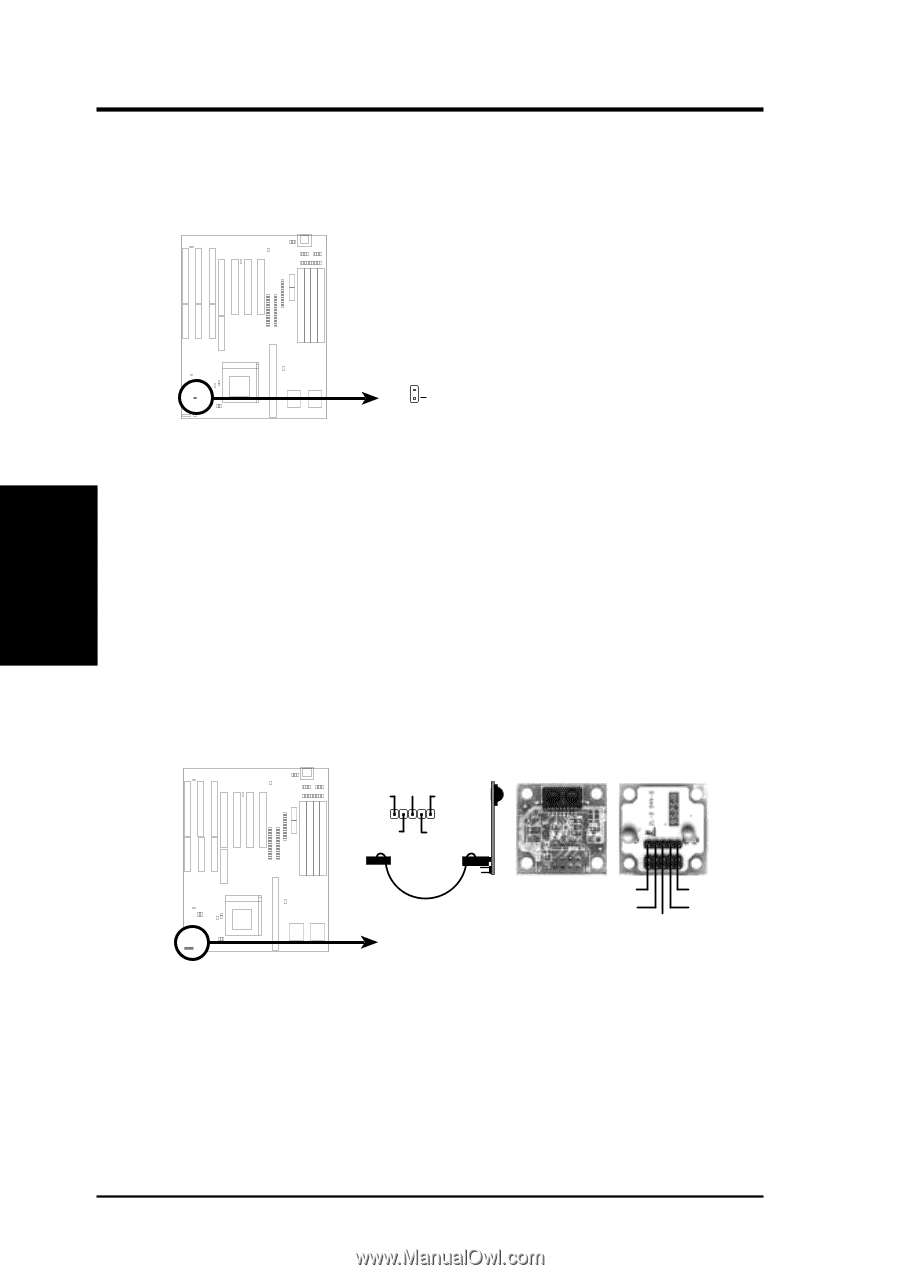
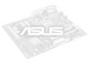
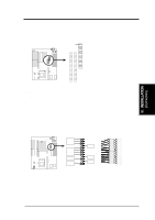
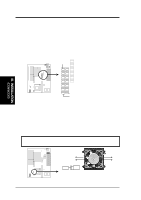
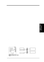
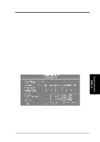
III. INSTALLATION (Connectors) III. INSTALLATION 14. IDE activity LED (JP17) This connector connects to the hard disk activity indicator light on the case. JP17 + IDE (Hard Drive) LED 16. IrDA-compliant infrared module connector (JP31) This connector supports the optional wireless transmitting and receiving infrared module. This module mounts to a small opening on system cases that support this feature. You must also configure the setting through BIOS setup on page 36 to select whether UART2 is directed for use with COM2 or IrDA. Use the five pins (as defined by Intel) as shown on the Back View and connect a ribbon cable from the module to the motherboard according to the pin definitions. The ribbon cable that may be supplied may either have five or ten pins (for other standards). If using a ten-pin ribbon cable, use only the top five row of the ribbon cable plug. IRRX +5V IRTX NC GND Front View Back View Infrared Module Connector (JP31) IRTX +5V GND NC IRRX 24 P/I-P55TP4N User's Manual
-
 1
1 -
2
-
3
-
4
-
5
-
6
-
7
-
8
-
9
-
10
-
11
-
12
-
13
-
14
-
15
-
16
-
17
-
18
-
19
-
20
-
21
-
22
-
23
-
24
-
 25
25 -
 26
26 -
 27
27 -
 28
28 -
 29
29 -
 30
30 -
 31
31 -
 32
32 -
 33
33 -
 34
34 -
 35
35 -
36
-
37
-
38
-
39
-
40
-
41
-
42
-
43
-
44
-
45
-
46
-
47
-
48
-
49
-
50
-
51
-
52
-
53
-
54
-
55
-
56
-
57
-
58
-
59
-
60
-
61
-
62
-
63
-
64
 |
 |