Asus P I-P55TP4N User Manual - Page 42
P/I-P55TP4N User's Manual, UART2 Use Infrared, Onboard PCI IDE Enable, IDE 0 Master/Slave Mode, IDE
 |
View all Asus P I-P55TP4N manuals
Add to My Manuals
Save this manual to your list of manuals |
Page 42 highlights
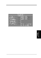
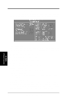
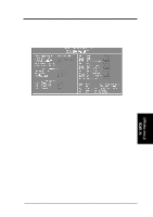
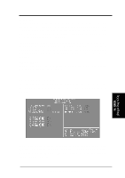
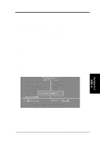
IV. BIOS SOFTWARE UART2 Use Infrared When enabled, this field activates the onboard infrared feature and sets the second serial UART to support the infrared module connector on the motherboard. If your system already has a second serial port connected to the onboard COM2 connector, it will no longer work if you enable the infrared feature. By default, this field is set to Disabled, which leaves the second serial port UART to support the COM2 serial port connector. See page 24 for the Infrared Connector. Onboard PCI IDE Enable You can select to enable the primary IDE channel, secondary IDE channel, both (default), or disable both channels (for systems with only SCSI hard drives). IDE 0 Master/Slave Mode, IDE 1 Master/Slave Mode Each channel (0 and 1) has both a master and a slave making four IDE devices possible. Because each IDE device may have a different Mode timing (0, 1, 2, 3, 4), it is necessary for these to be independent. The default setting of Auto will allow auto-detection to ensure the optimal performance. IV. BIOS (Chipset Features) IV. BIOS (Chipset Features) 36 P/I-P55TP4N User's Manual
-
 1
1 -
2
-
3
-
4
-
5
-
6
-
7
-
8
-
9
-
10
-
11
-
12
-
13
-
14
-
15
-
16
-
17
-
18
-
19
-
20
-
21
-
22
-
23
-
24
-
25
-
26
-
27
-
28
-
29
-
30
-
31
-
32
-
33
-
34
-
35
-
36
-
 37
37 -
 38
38 -
 39
39 -
 40
40 -
 41
41 -
 42
42 -
 43
43 -
 44
44 -
 45
45 -
 46
46 -
 47
47 -
48
-
49
-
50
-
51
-
52
-
53
-
54
-
55
-
56
-
57
-
58
-
59
-
60
-
61
-
62
-
63
-
64
 |
 |