Asus P I-P55TP4N User Manual - Page 26
P/I-P55TP4N User's Manual, Parallel Printer Connector 26 Pin Block, Serial port COM1 and COM2
 |
View all Asus P I-P55TP4N manuals
Add to My Manuals
Save this manual to your list of manuals |
Page 26 highlights
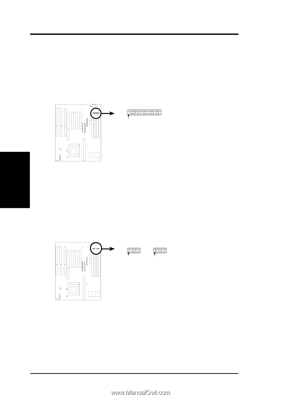
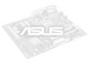
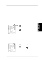
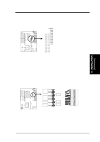
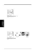
III. INSTALLATION (Connectors) III. INSTALLATION 3. Parallel Printer Connector (26 Pin Block) Connection for the included parallel port ribbon cable with mounting bracket. Connect the ribbon cable to this connection and mount the bracket to the case on an open slot. It will then be available for a parallel printer cable. Note: Serial printers must be connected to the serial port. You can enable the parallel port and choose the IRQ through BIOS Setup on page 35 "Onboard Parallel Port." Pin 1 Parallel (Printer) Connector 4. Serial port COM1 and COM2 connectors (Two 10-pin blocks) These connectors support the provided serial port ribbon cables with mounting bracket. Connect the ribbon cables to these connectors and mount the bracket to the case on an open slot. The two serial ports on the mounting bracket will then be used for pointing devices or other serial devices. See page 35 for BIOS configuration of "Onboard Serial Port" COM 1 COM 2 Pin 1 Pin 1 Serial Port Connectors 20 P/I-P55TP4N User's Manual
-
 1
1 -
2
-
3
-
4
-
5
-
6
-
7
-
8
-
9
-
10
-
11
-
12
-
13
-
14
-
15
-
16
-
17
-
18
-
19
-
20
-
 21
21 -
 22
22 -
 23
23 -
 24
24 -
 25
25 -
 26
26 -
 27
27 -
 28
28 -
 29
29 -
 30
30 -
 31
31 -
32
-
33
-
34
-
35
-
36
-
37
-
38
-
39
-
40
-
41
-
42
-
43
-
44
-
45
-
46
-
47
-
48
-
49
-
50
-
51
-
52
-
53
-
54
-
55
-
56
-
57
-
58
-
59
-
60
-
61
-
62
-
63
-
64
 |
 |