Asus P I-P55TP4N User Manual - Page 41
Onboard Serial Port 1 / Onboard Serial Port 2
 |
View all Asus P I-P55TP4N manuals
Add to My Manuals
Save this manual to your list of manuals |
Page 41 highlights
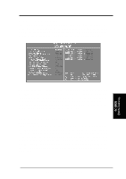
(Chipset Features) IV. BIOS SOFTWARE Onboard FDC Controller When enabled, this field allows you to connect your floppy disk drives to the onboard floppy drive connector instead of a separate controller card. If you want to use a different controller card to connect the floppy drives, set this field to "Disabled". Default setting is "Enabled". Onboard FDC Swap A: B: This field reverses the drive letter assignments of your floppy disk drives. Two options are available: "No Swap" and "Swap AB". "No Swap" is the default setting. If you want to switch drive letter assignments, set this field to "Swap AB", and the swap will be controlled in hardware. This works separately from the BIOS Features floppy disk swap feature. It is functionally the same as physically interchanging the connectors of the floppy disk drives. Onboard Serial Port 1 / Onboard Serial Port 2 These fields control the assignments for the motherboard's two onboard serial connectors. The following lists the available options: COM1, 3F8H (Onboard Serial Port 1 default) COM2, 2F8H (Onboard Serial Port 2 default) COM3, 3E8H COM4, 2E8H Disabled (Disables the onboard serial ports) Onboard Parallel Port This field sets the address of the onboard parallel port connector. You can select either: 3BCH / IRQ 7, 378H / IRQ 7 (default), 278H / IRQ 5, Disabled. If you install an I/O card with a parallel port, ensure that there is no conflict in the address assignments. The PC can support up to three parallel ports as long as there are no conflicts for each port. Parallel Port Mode This field allows you to set the operation mode of the parallel port. The default setting Normal, allows normal-speed operation but in one direction only; EPP allows bidirectional parallel port operation at maximum speed; ECP allows the parallel port to operate in bidirectional mode and at a speed faster than the maximum data transfer rate; ECP+EPP allows normal speed operation in a two-way mode. ECP DMA Select This selection is available only if you select ECP or ECP+EPP in the Parallel Port Mode. Select either DMA Channel 1, 3, or Disable. The setup default is DMA Channel 3. IV. BIOS (Chipset Features) P/I-P55TP4N User's Manual 35
-
 1
1 -
2
-
3
-
4
-
5
-
6
-
7
-
8
-
9
-
10
-
11
-
12
-
13
-
14
-
15
-
16
-
17
-
18
-
19
-
20
-
21
-
22
-
23
-
24
-
25
-
26
-
27
-
28
-
29
-
30
-
31
-
32
-
33
-
34
-
35
-
 36
36 -
 37
37 -
 38
38 -
 39
39 -
 40
40 -
 41
41 -
 42
42 -
 43
43 -
 44
44 -
 45
45 -
 46
46 -
47
-
48
-
49
-
50
-
51
-
52
-
53
-
54
-
55
-
56
-
57
-
58
-
59
-
60
-
61
-
62
-
63
-
64
 |
 |
