Asus P I-P55TP4N User Manual - Page 25
External Connectors
 |
View all Asus P I-P55TP4N manuals
Add to My Manuals
Save this manual to your list of manuals |
Page 25 highlights
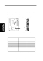
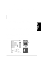
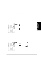
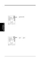
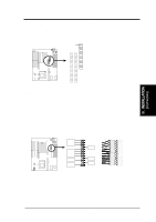
III. INSTALLATION 5. External Connectors IMPORTANT: Ribbon cables should always be connected with the red stripe on the Pin 1 side of the connector. The four corners of the connectors are labeled on the motherboard. Pin 1 is the side closest to the power connector on hard drives and floppy drives. IDE ribbon cable must be less than 18in. (46cm), with the second drive connector no more than 6in. (15cm) from the first connector. 1. Keyboard Connector (5-pin female) This connection is for a standard IBM-compatible keyboard. May also be known as a 101 enhanced keyboard. III. INSTALLATION (Connectors) Keyboard Connector (5-pin female) Connector Plug from Keyboard 2. PS/2 Mouse Connector (6-pin block) If you are using a PS/2 mouse, you must purchase an optional PS/2 mouse set which connects to the 6 pin block and mounts to an open slot on your computer's case. You must also set "PS/2 Mouse Selection" on page 11 to enable the PS/2 Mouse. 1 234 58 1 234 58 1: GND 2: DATA 3: NC 4: VCC 5: CLK 8: NC PS/2 Mouse Module Connector P/I-P55TP4N User's Manual 19
-
 1
1 -
2
-
3
-
4
-
5
-
6
-
7
-
8
-
9
-
10
-
11
-
12
-
13
-
14
-
15
-
16
-
17
-
18
-
19
-
 20
20 -
 21
21 -
 22
22 -
 23
23 -
 24
24 -
 25
25 -
 26
26 -
 27
27 -
 28
28 -
 29
29 -
 30
30 -
31
-
32
-
33
-
34
-
35
-
36
-
37
-
38
-
39
-
40
-
41
-
42
-
43
-
44
-
45
-
46
-
47
-
48
-
49
-
50
-
51
-
52
-
53
-
54
-
55
-
56
-
57
-
58
-
59
-
60
-
61
-
62
-
63
-
64
 |
 |
