Asus P I-P55TP4N User Manual - Page 15
Total Level 2 Cache Size Setting
 |
View all Asus P I-P55TP4N manuals
Add to My Manuals
Save this manual to your list of manuals |
Page 15 highlights
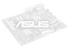
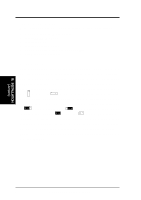
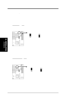
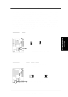
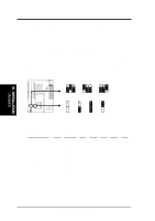
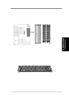
III. INSTALLATION 3. Total Level 2 Cache Size Setting (JP16) This jumper sets the total amount of L2 cache that is present. If you have two cache chips onboard (see "Map of Motherboard" for locations), then you have either 256KB or 512KB. An "ASUS" or "COAST" cache module can be used to upgrade the 256KB version to 512KB. If there is no onboard cache, you must install a cache module of either 256KB or 512KB. IMPORTANT: See page 14 "SRAM Cache" for installation procedures. Regardless of your cache combination, set the following jumpers according to the total amount of L2 cache that is present onboard and installed as a module. Selections 256KB 512KB JP16 [2-3] (Default) [1-2] JP16 JP16 1 2 3 256KB 1 2 3 512KB Total L2 Cache Size Setting (256KB / 512KB) 4. Voltage Regulator Output Selection (JP22, 23, 24) These jumpers set the voltage supplied to the CPU. Selections JP24 JP23 JP22 STD 3.3V-3.465V [open] [open] [short] (Default) VRE 3.4V-3.6V [open] [short] [open] III. INSTALLATION (Jumpers) JP22 JP23 JP24 JP22 JP23 JP24 STD 3.3V - 3.465V (Default) VRE 3.4V - 3.6V Voltage Regulator Output Selection (STD / VRE) P/I-P55TP4N User's Manual 9
-
 1
1 -
2
-
3
-
4
-
5
-
6
-
7
-
8
-
9
-
 10
10 -
 11
11 -
 12
12 -
 13
13 -
 14
14 -
 15
15 -
 16
16 -
 17
17 -
 18
18 -
 19
19 -
 20
20 -
21
-
22
-
23
-
24
-
25
-
26
-
27
-
28
-
29
-
30
-
31
-
32
-
33
-
34
-
35
-
36
-
37
-
38
-
39
-
40
-
41
-
42
-
43
-
44
-
45
-
46
-
47
-
48
-
49
-
50
-
51
-
52
-
53
-
54
-
55
-
56
-
57
-
58
-
59
-
60
-
61
-
62
-
63
-
64
 |
 |