Asus P I-P55TP4N User Manual - Page 12
Installation Steps, Jumpers
 |
View all Asus P I-P55TP4N manuals
Add to My Manuals
Save this manual to your list of manuals |
Page 12 highlights
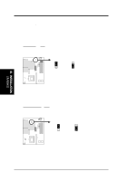
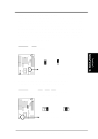
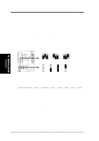
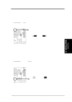
III. INSTALLATION Installation Steps Before using your computer, you must follow the six steps as follows: 1. Set Jumpers on the Motherboard 2. Install DRAM Modules 3. Install the CPU 4. Install Expansion Cards 5. Connect Cables, Wires, and Power Supply 6. Setup the BIOS Software 1. Jumpers Several hardware settings are made through the use of jumper caps to con- nect jumper pins (JP) on the motherboard. See "Map of the Motherboard" on page 4 for locations of jumpers. The jumper settings will be described numerically such as [----], [1-2], [2-3] for no connection, connect pins 1&2, and connect pins 2&3 respectively. Pin 1 for our motherboards is always on Pin 1 Pin 1 top or on the left when holding the motherboard with the key- board connector away from yourself. A "1" is written besides pin 1 on jumpers with three pins. The jumpers will also be shown graphically such as to connect pins 1&2 and to connect pins 2&3. Jumpers with two pins will be shown as for short and for open. For manufactur- ing simplicity, the jumpers may be sharing pins from other groups. Use the diagrams in this manual instead of following the pin layout on the board. Settings with two jumper numbers require that both jumpers be moved to- gether. To connect the pins, simply place a plastic jumper cap over the two pins as diagramed. III. INSTALLATION (Jumpers) 6 P/I-P55TP4N User's Manual
-
 1
1 -
2
-
3
-
4
-
5
-
6
-
 7
7 -
 8
8 -
 9
9 -
 10
10 -
 11
11 -
 12
12 -
 13
13 -
 14
14 -
 15
15 -
 16
16 -
 17
17 -
18
-
19
-
20
-
21
-
22
-
23
-
24
-
25
-
26
-
27
-
28
-
29
-
30
-
31
-
32
-
33
-
34
-
35
-
36
-
37
-
38
-
39
-
40
-
41
-
42
-
43
-
44
-
45
-
46
-
47
-
48
-
49
-
50
-
51
-
52
-
53
-
54
-
55
-
56
-
57
-
58
-
59
-
60
-
61
-
62
-
63
-
64
 |
 |