Asus P I-P55TP4N User Manual - Page 28
P/I-P55TP4N User's Manual, Primary / Secondary IDE connectors, Two 40-pin Block, CPU cooling fan
 |
View all Asus P I-P55TP4N manuals
Add to My Manuals
Save this manual to your list of manuals |
Page 28 highlights
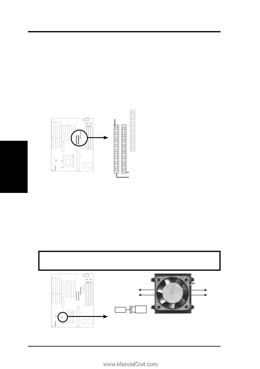
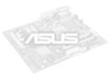
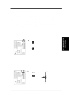
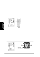
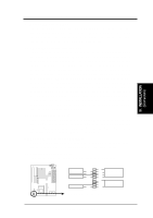
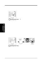
III. INSTALLATION 7. Primary / Secondary IDE connectors (Two 40-pin Block) This connector supports the provided IDE hard disk ribbon cable. After connecting the single end to the board, connect the two plugs at the other end to your hard disk(s). If you install two hard disks, you must configure the second drive to Slave mode by setting its jumpers accordingly. Please refer to the documentation of your hard disk for the jumper settings. You may also configure two hard disks to be both Masters using one ribbon cable on the primary IDE connector and another ribbon cable on the secondary IDE connector. Pin 1 III. INSTALLATION (Connectors) Secondary IDE Connector Primary IDE Connector 8. CPU cooling fan connector (JP30) This connector supports a CPU cooling fan of 500mAMP (6WATT) or less. Orientate the fan so that the heat sink fins run perpendicular to the expansion slots. This will allow air flow to go across the onboard heat sink(s) instead of the expansion slots. Depending on the fan manufacturer, the wiring and plug may be different. The red wire should be positive, while the black should be ground. Connect the fan's plug to the board taking into consideration the polarity of the this connector. WARNING: Damage may occur to the motherboard and/or the CPU fan if these pins are incorrectly used. Air Flow JP30 +12V GND CPU Fan Power Air Flow 22 P/I-P55TP4N User's Manual
-
 1
1 -
2
-
3
-
4
-
5
-
6
-
7
-
8
-
9
-
10
-
11
-
12
-
13
-
14
-
15
-
16
-
17
-
18
-
19
-
20
-
21
-
22
-
 23
23 -
 24
24 -
 25
25 -
 26
26 -
 27
27 -
 28
28 -
 29
29 -
 30
30 -
 31
31 -
 32
32 -
 33
33 -
34
-
35
-
36
-
37
-
38
-
39
-
40
-
41
-
42
-
43
-
44
-
45
-
46
-
47
-
48
-
49
-
50
-
51
-
52
-
53
-
54
-
55
-
56
-
57
-
58
-
59
-
60
-
61
-
62
-
63
-
64
 |
 |