Bowflex Power Pro Assembly Manual
Bowflex Power Pro Manual
 |
View all Bowflex Power Pro manuals
Add to My Manuals
Save this manual to your list of manuals |
Bowflex Power Pro manual content summary:
- Bowflex Power Pro | Assembly Manual - Page 1
BOWFLEX ® Power Pro ASSEMBLY MANUAL Includes Instructions for Bowflex Power Pro Attachments and Upgrades. - Bowflex Power Pro | Assembly Manual - Page 2
Bowflex Power Pro 4-10 Part Reference and Size Guide 4 PowerPro Reference Guide 5 Assembly Instructions 6-10 Leg Extension Attachment 11-13 Part Reference and Size Guide 11 Assembly Instructions 12-13 Chest Bar Attachment 14-17 Assembly Instructions 15-17 Lat Pulldown Attachment 18-22 Part - Bowflex Power Pro | Assembly Manual - Page 3
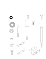
head (+) screw driver. Please follow these assembly instructions carefully. If you experience any difficulty, please call a Bowflex customer service representative and ask for assistance. 1-800-269-3539. Bowflex Power Pro Parts Reference Guide Name: 1/4" Washer Part #: 90156 Quantity: 1 Name: #12 - Bowflex Power Pro | Assembly Manual - Page 4
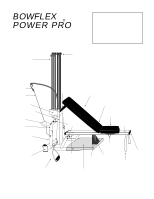
. Power Rods Rod Cap Hook Cable Rod Box Vertical Mainframe Pulley U-Bar Main Frame 3" End Cap Hand Grip Ankle Cuff Incline Support Bracket Bench Bench Cup (Not Visible, under Bench) Seat Non Skid Pads Seat Rail Pivot Bracket (Not Visible) Riser Support Bracket Standing Platform Seat - Bowflex Power Pro | Assembly Manual - Page 5
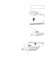
the Power Pro Components for this assembly are in Boxes 2 and 3 Seat Rail Channel 1a. Rear Leg Bolt Keeper (marked with an R) Once you have both bolt keepers in place, install the Rear Leg - place four 3/8" washers and tighten a 3/8" nylon locknut on to each of the bolts. Riser Bracket - Bowflex Power Pro | Assembly Manual - Page 6
you purchased a CHEST BAR attachment, do not install the u-bar as shown in step 3. Instead, go now to page 16, step 5, of the chest bar assembly instructions. Components for this assembly are in Boxes 2 and 3 2a. Bench Seat Quick Release Hinge End Cap 2b. Seat Rail Slide Seat onto Seat Rail - Bowflex Power Pro | Assembly Manual - Page 7
line up. Secure the two parts together by tightening four of the #12 Screws through the four holes (two on each side) of the Power Rod Pack. Note: If the screws do not go in easily, use soap or other lubricant in screw threads. 5a. Power Rod Pack Components for this assembly are in Box 1 Vertical - Bowflex Power Pro | Assembly Manual - Page 8
. To check for proper adjustment, attach the Bench to the Seat. (They connect by a Quick Release Hinge.) Lock Seat Pin into the fourth hole of the side channel of the Seat Rail. Adjust Bracket position so that contact is made with top of Rod Pack as pictured. After Bracket has been adjusted, tighten - Bowflex Power Pro | Assembly Manual - Page 9
Bowflex. Unwrap Cables and Pulleys. Locate Nonskid Pads. Remove paper backing to expose the adhesive surface. Adhere Nonskid Pads to Pulley Frame as shown. Note: If you installed a CHEST BAR Attachment, please go to page 16, step 8. Place Nonskid Pads here (facing top) Components for this assembly - Bowflex Power Pro | Assembly Manual - Page 10
this assembly are in a box labeled Leg Extension Attachment Box Contents 1 Leg Extension Main Frame (with pre-attached pulleys (2) and left & right brackets.) 1 Leg Extension Pivot Arm 1 Leg Extension Foot 1 Seat (with four "L" brackets attached) 3 Metal Tubes 6 Foam Pads 2 68" Cable 1 Parts/Bolt - Bowflex Power Pro | Assembly Manual - Page 11
Installing the Leg Extension Attachment Components for this assembly are in a box labeled Leg Extension Attachment Step 1: Rotate Pivot Arm Bracket as indicated. Step 2: Secure Pivot Arm Bracket by inserting one 5/16" x 2" Hex Head Bolt through indicated hole on Bracket and tighten with one 5/16" - Bowflex Power Pro | Assembly Manual - Page 12
Arm Assembly does not have excessive side to side movement, but still pivots smoothly. Step 6: Attach Leg Extension to Bowflex by sliding Bench forward, then placing Leg Extension Bracket onto end of Seat Rail. Secure by inserting the "L" Pin through the two holes on Leg Extension Bracket. Make - Bowflex Power Pro | Assembly Manual - Page 13
call a Bowflex customer service representative and ask for assistance at 1-800-269-3539. Components for this assembly are in a box labeled Chest Bar Attachment Contents of box 1 Chest Bar 2 Non-skid Pads Exercise Instruction Sheet Assembly Instructions Please check to make sure all parts are - Bowflex Power Pro | Assembly Manual - Page 14
Instructions Step 1: Slide Seat to end of seat rail and lower to flat position. Components for this assembly are in a box labeled Chest Bar Attachment Step 2: Remove indicated bolts going through pulley frame and Vertical Main Frame. Vertical Main Frame Remove the Vertical Main Frame with Rod - Bowflex Power Pro | Assembly Manual - Page 15
that you previously removed in Step Two, attach Chest Bar to machine frame. Tighten securely. Note: Once you finish installing your chest bar, go back to page 8, step 4 and continue assembling your Bowflex. Step 7: Replace the Vertical Main Frame with Rod Pack that you removed in step two. Secure - Bowflex Power Pro | Assembly Manual - Page 16
, approximately the same width as the U-Bar that was previously attached to your Power Pro. 2) Extended Position for enhancing your chest and shoulder exercises. To extend your bar, simply untighten the adjustment knobs on the back of the bar and slide chest bar out until it reaches last notch and - Bowflex Power Pro | Assembly Manual - Page 17
not be included. Components for this assembly are in a box labeled Lat Pulldown Attachment Box Contents 1 Cross Bar 1 Main Frame Lower Half 1 Upper Main Frame 2 Main Frame Brackets 1 T-Piece with pulley, and Rest Brackets 2 59" Cables 1 48" Long Bar 1 Parts/Bolt Bag Name: 3/8" x 3 1/2" Hex Head - Bowflex Power Pro | Assembly Manual - Page 18
for this assembly are in a box labeled Lat Pulldown Attachment Step 1: Remove the long portion of the Bench. Step 2: Place the cross bar so the curved ends are facing downward and they rest on the bottom of the pulley frame. Main Frame (Lower Half) Vertical Extrusion Seat Rail Cross Bar Top View - Bowflex Power Pro | Assembly Manual - Page 19
Components for this assembly are in a box labeled Lat Pulldown Attachment Step 4: Locate the Main Frame Brackets. Place one bracket over the Main Frame Lower Half - just above the crossbar. Place the other bracket on the Main Frame just below the Power Rod pack. Main Frame Brackets Wing Nuts Main - Bowflex Power Pro | Assembly Manual - Page 20
Components for this assembly are in a box labeled Lat Pulldown Attachment Upper Main Frame Step 6: Locate Upper Main Hex Head Bolts 3/8" Nylon Locknut "T" Piece NOTICE: For shipping purposes, the Lat Bar Rest brackets have been turned to the sides. Notice their correct positioning in the diagram - Bowflex Power Pro | Assembly Manual - Page 21
the 30 pound Power Rods on each side at this time. Locate the Long Bar. Attach the Long Bar to the cables by hanging them from the Lat Pulldown Attachment with the supplied Snap Hooks. IMPORTANT! Place Lat Bar in Brackets when not in use. Note: With the addition of your new lat tower, the angle of - Bowflex Power Pro | Assembly Manual - Page 22
use those Snap Hooks to attach Pulleys to holes on sides of Squat Plate. To use, attach Squat Bar and Chains (as needed) to Cable Ends. Then, attach small Cable Ends to Power Rod Cables. Caution: Be sure to remove Squat Plate before folding and transporting the Bowflex. • Always wear shoes with - Bowflex Power Pro | Assembly Manual - Page 23
BICEPS CURL START FINISH Keep back flat - do not arch. Lift with your legs not your back. Keep your knees bent and your head up. BARBELL BICEPS CURL not arch. LYING TRICEPS PRESS START FINISH Keep knees slightly bent. STIFF LEG DEAD LIFT START FINISH Keep elbows out in front of you. Adjust - Bowflex Power Pro | Assembly Manual - Page 24
. Depending on the machine and accessories you ordered, this attachment may or may not be included. H Step 1: Lay your Foot Harness out as shown in the illustration to the left and follow the instructions for proper usage. All Straps and Rings are labeled alphabetically for your convenience - Bowflex Power Pro | Assembly Manual - Page 25
and fold excess back and attach with velcro. Assembling Your Bowflex T-Bar Your t-bar was shipped fully assembled with the metal bar resting in the loops of the nylon strap. If, however, the bar and the nylon strap separated during shipping, follow these instructions for reassembly. Step 1: The - Bowflex Power Pro | Assembly Manual - Page 26
pack by removing the four screws on the back of the Base. To expand your Bowflex from 310 lbs. to 410 lbs.: Step 1: Simply slide in new rods to the back of the Power Rod Base. Make sure new Rods are fully seated into Base before using. Step 2: Step 3: Remove plugs in the first two holes of the - Bowflex Power Pro | Assembly Manual - Page 27
. Inc. The Nautilus Group, Inc. 1400 N.E. 136th Ave., Vancouver, WA 98684 Bowflex and the Bowflex logo are registered trademarks of The Nautilus Group, Inc. - a NYSE-listed company © 2002,The Nautilus Group, Vancouver, WA 98684 PN80159 Power Pro Assembly Manual Rev 3.0 (02/03) Doc. # EN 100002
-
 1
1 -
 2
2 -
 3
3 -
 4
4 -
 5
5 -
 6
6 -
 7
7 -
8
-
9
-
10
-
11
-
12
-
13
-
14
-
15
-
16
-
17
-
18
-
19
-
20
-
21
-
22
-
23
-
24
-
25
-
26
-
27
 |
 |
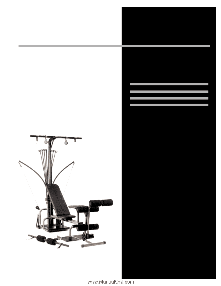
BOWFLEX
®
Power Pro
Includes Instructions
for Bowflex Power Pro
Attachments and
Upgrades.
ASSEMBLY
MANUAL