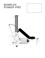
Bowflex Power Pro Assembly Manual - Page 8
Step 6, Step 7
 |
View all Bowflex Power Pro manuals
Add to My Manuals
Save this manual to your list of manuals |
Page 8 highlights
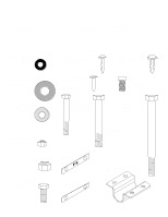
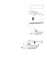
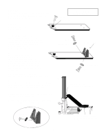
Step 6: Now locate the Bench. Turn Bench upside down. Place the Bench Cup between the two hinges. Secure with a #14 Screw. Step 7: Now locate the Incline Support Bracket. 7a. Place Bracket on Bench as shown. Insert Tap Bolts with 5/16" Flat Washer through Bracket and hand tighten. Do not tighten with a wrench yet. Bracket needs to be adjusted to rest properly against the top of the Vertical Main Frame. 7b. To check for proper adjustment, attach the Bench to the Seat. (They connect by a Quick Release Hinge.) Lock Seat Pin into the fourth hole of the side channel of the Seat Rail. Adjust Bracket position so that contact is made with top of Rod Pack as pictured. After Bracket has been adjusted, tighten securely with a 1/2" open end wrench. 7c. Next, remove bench and insert and tighten a #14 screw into center notch of the bracket as shown below. There is no pre-drilled hole for this. #14 Screw Bench Cup Components for this assembly are in Box 2 7a. Tap Bolt 5/16" Flat Washer Incline Support Bracket 1/4" washer 5/16" Flat Washer Tap Bolt 7b. Incline Support Bracket sits properly against Vertical Main Frame. SAFETY NOTE: Double check to make sure bench is stable in the incline position. Before using the bench make sure all three screws are in place and securely tightened 1/4" Washer #14 Screw Pull Pin out and turn clockwise, one quarter turn to lock Seat into position. 9
-
 1
1 -
2
-
 3
3 -
 4
4 -
 5
5 -
 6
6 -
 7
7 -
 8
8 -
 9
9 -
 10
10 -
 11
11 -
 12
12 -
 13
13 -
14
-
15
-
16
-
17
-
18
-
19
-
20
-
21
-
22
-
23
-
24
-
25
-
26
-
27
 |
 |
