Bowflex Power Pro Assembly Manual - Page 6
Step 3, Step 2 - assembly instructions
 |
View all Bowflex Power Pro manuals
Add to My Manuals
Save this manual to your list of manuals |
Page 6 highlights
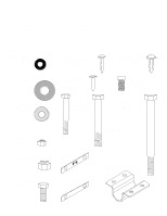
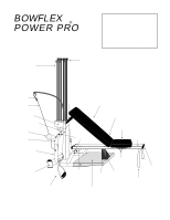
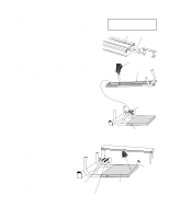
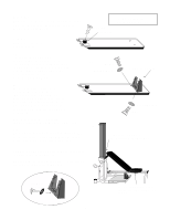
Step 2: Locate Seat and Bench and separate from one another. They are connected by a Quick Release Hinge. See illustration 2a at right. 2b. The seat slides onto the Seat Rail by aligning the wheels on the Seat with the channels along the sides of the Seat Rail. Pull out the Seat Locking Pin in order to slide the Seat on. Seat Pin locks Seat into position. Pulling pin out and turning counterclockwise one quarter turn allows Seat to slide freely. After you have installed the Seat, you can install the two End Caps at the ends of the Seat Rail. Secure them with the #10 Screws. (smallest screws) If the screws are not going in, you can use soap or other lubricant on the screw threads. Note: If you purchased a CHEST BAR attachment, do not install the u-bar as shown in step 3. Instead, go now to page 16, step 5, of the chest bar assembly instructions. Components for this assembly are in Boxes 2 and 3 2a. Bench Seat Quick Release Hinge End Cap 2b. Seat Rail Slide Seat onto Seat Rail #10 Screw Side Channels End Cap Seat Lock Pin (Pull Out) Step 3: Locate the U-Bar. Insert U-Bar into the openings of the Main Frame and secure with two 1/4" x 2" Hex Head Bolts and two 1/4" Nylon Lock Nuts. Leave loose until Step 4. Note: Do not unwrap Pulleys and Cables until you are finished with full assembly. Components for this assembly are in Boxes 2 and 3 U-Bar 1/4" x 2" Hex Head Bolts 1/4" Nylon Lock Nut 7
-
 1
1 -
 2
2 -
 3
3 -
 4
4 -
 5
5 -
 6
6 -
 7
7 -
 8
8 -
 9
9 -
 10
10 -
 11
11 -
 12
12 -
13
-
14
-
15
-
16
-
17
-
18
-
19
-
20
-
21
-
22
-
23
-
24
-
25
-
26
-
27
 |
 |
