Brother International 9870 Service Manual - Page 157
This selector sets the time length from when the machine detects the PC powered off until
 |
View all Brother International 9870 manuals
Add to My Manuals
Save this manual to your list of manuals |
Page 157 highlights
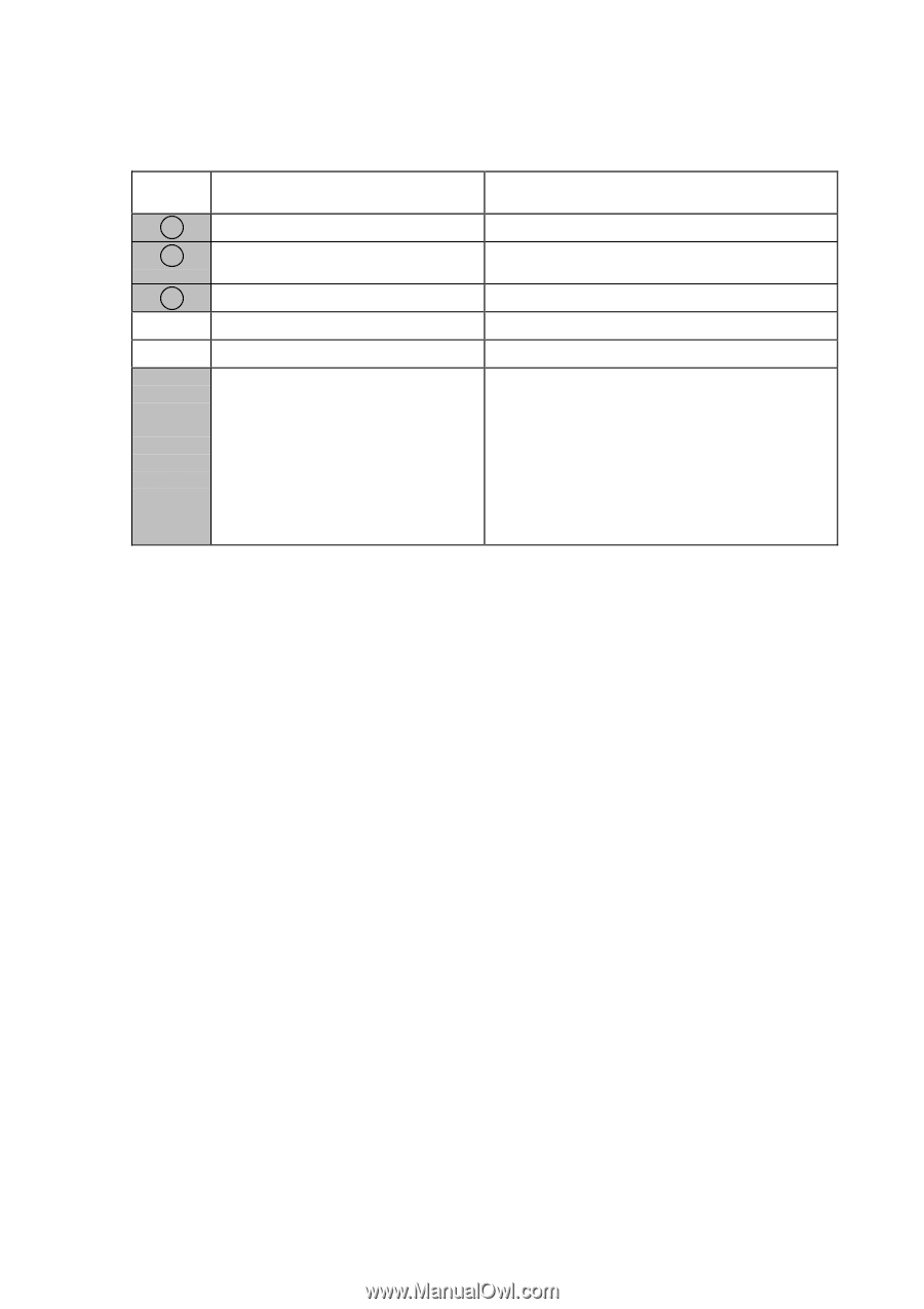
WSW36 (Function setting 14) Selector No. 1 2 Function ECP* mode Recovery from inactive PC interface Setting and Specifications 0: ON 1: OFF 0: Disabled 1: Enabled 3 PC power-off recognition time 0: Normal 1: Long 4 Not used. 5 Escape from phase C 0: Yes 1: No No. 6 7 8 0 0 0 : 0 (Not ignored) 0 0 1 : 4 (448 Hz) 6 Lower limit of frequency to be | ignored after detection of calling 8 signals (Ci) 0 10: 0 11: 1 00: 1 01: 8 (244 Hz) 12 (162 Hz) 16 (122 Hz) 20 (97 Hz) 1 1 0 : 24 (81 Hz) 1 1 1 : 28 (69 Hz) l Selector 1: ECP mode *ECP (Enhanced Capabilities Port) The ECP mode enhances the normal bidirectional communications between the machine and the connected PC for higher transmission speed. l Selector 2: Recovery from inactive PC interface If the machine recognizes via the STB signal line that the connected PC is powered off, it will turn the PC interface outputs Low to protect the PC from hazards that could be caused by weak electric current accidentally flown from the machine. This selector determines whether the machine should recover from the inactive PC interface to normal interfacing state upon receipt of data from the PC. l Selector 3: PC power-off recognition time This selector sets the time length from when the machine detects the PC powered off until it recognizes the detected state as power-off. If selector 2 is set to "0," it is recommended that selector 3 be set to "1": otherwise, the machine may mistakenly detect PC powered off. l Selector 5: Escape from phase C This selector determines whether or not the machine will escape from phase C when it detects an RTC (Return to Control) in non-ECM mode or an RCP (Return to Control Partial page) in ECM mode. l Selectors 6 through 8: Lower limit of frequency to be ignored after detection of calling signals (Ci) At the start of reception, if the machine detects the frequency of calling signals (Ci) specified by selectors 1 through 4 of WSW14, it will start the ringer sounding. When doing so, the machine may fail to detect the calling signals normally due to noises superimposed at the time of reception. To prevent it, use selectors 6 through 8 of WSW36. If the machine detects higher frequencies than the lower limit specified by these selectors, it will regard them as noise and interpret that detecting state as being normal, allowing the ringer to keep sounding (until the machine starts automatic reception of FAX data if in the FAX mode, according to the preset number of ringers). V - 45
-
 1
1 -
2
-
3
-
4
-
5
-
6
-
7
-
8
-
9
-
10
-
11
-
12
-
13
-
14
-
15
-
16
-
17
-
18
-
19
-
20
-
21
-
22
-
23
-
24
-
25
-
26
-
27
-
28
-
29
-
30
-
31
-
32
-
33
-
34
-
35
-
36
-
37
-
38
-
39
-
40
-
41
-
42
-
43
-
44
-
45
-
46
-
47
-
48
-
49
-
50
-
51
-
52
-
53
-
54
-
55
-
56
-
57
-
58
-
59
-
60
-
61
-
62
-
63
-
64
-
65
-
66
-
67
-
68
-
69
-
70
-
71
-
72
-
73
-
74
-
75
-
76
-
77
-
78
-
79
-
80
-
81
-
82
-
83
-
84
-
85
-
86
-
87
-
88
-
89
-
90
-
91
-
92
-
93
-
94
-
95
-
96
-
97
-
98
-
99
-
100
-
101
-
102
-
103
-
104
-
105
-
106
-
107
-
108
-
109
-
110
-
111
-
112
-
113
-
114
-
115
-
116
-
117
-
118
-
119
-
120
-
121
-
122
-
123
-
124
-
125
-
126
-
127
-
128
-
129
-
130
-
131
-
132
-
133
-
134
-
135
-
136
-
137
-
138
-
139
-
140
-
141
-
142
-
143
-
144
-
145
-
146
-
147
-
148
-
149
-
150
-
151
-
 152
152 -
 153
153 -
 154
154 -
 155
155 -
 156
156 -
 157
157 -
 158
158 -
 159
159 -
 160
160 -
 161
161 -
 162
162 -
163
-
164
-
165
-
166
-
167
-
168
-
169
-
170
-
171
-
172
-
173
-
174
-
175
-
176
-
177
-
178
-
179
-
180
-
181
-
182
-
183
-
184
-
185
-
186
-
187
-
188
-
189
-
190
-
191
-
192
-
193
-
194
-
195
-
196
-
197
-
198
-
199
-
200
-
201
-
202
-
203
-
204
-
205
-
206
-
207
-
208
-
209
-
210
-
211
-
212
-
213
-
214
-
215
-
216
-
217
-
218
-
219
-
220
-
221
-
222
-
223
-
224
-
225
-
226
-
227
-
228
-
229
-
230
-
231
-
232
-
233
-
234
-
235
-
236
-
237
-
238
-
239
-
240
-
241
-
242
-
243
-
244
-
245
-
246
-
247
-
248
-
249
-
250
-
251
-
252
-
253
-
254
-
255
-
256
-
257
-
258
-
259
-
260
-
261
-
262
-
263
-
264
-
265
-
266
-
267
-
268
-
269
-
270
-
271
-
272
-
273
-
274
-
275
-
276
-
277
-
278
-
279
-
280
-
281
-
282
-
283
-
284
-
285
-
286
 |
 |