Brother International 9870 Service Manual - Page 77
VC Cover, VC Bracket, and VC Connector PCB (for models supporting, Remove two screws d
 |
View all Brother International 9870 manuals
Add to My Manuals
Save this manual to your list of manuals |
Page 77 highlights
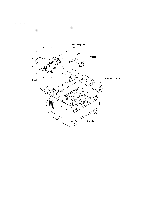
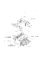
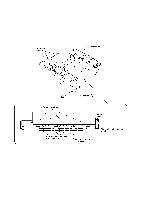
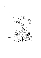
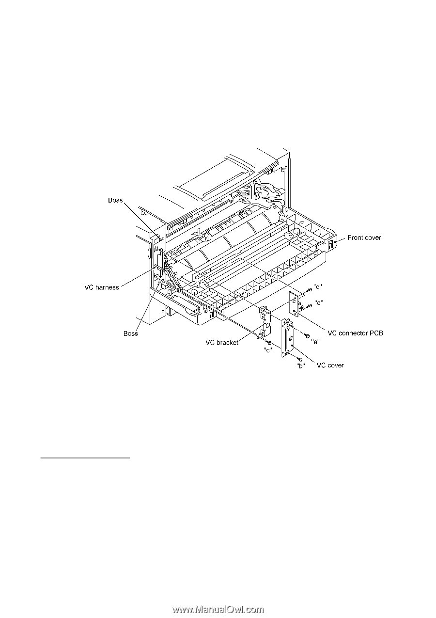
1.12 VC Cover, VC Bracket, and VC Connector PCB (for models supporting video capture) (1) Remove two screws ("a" and "b"), then take off the VC cover. (2) Remove screw "c," take out the VC bracket together with the VC connector PCB, and disconnect the VC harness. (3) Remove two screws "d," then take off the VC connector PCB. "a": Taptite, cup S M3x10 "b": Taptite, bind S M3x8 "c" and "d": Taptite, cup S M3x6 n Reassembling Notes • The routing of the VC harness is shown on page IV-34. IV - 31
-
 1
1 -
2
-
3
-
4
-
5
-
6
-
7
-
8
-
9
-
10
-
11
-
12
-
13
-
14
-
15
-
16
-
17
-
18
-
19
-
20
-
21
-
22
-
23
-
24
-
25
-
26
-
27
-
28
-
29
-
30
-
31
-
32
-
33
-
34
-
35
-
36
-
37
-
38
-
39
-
40
-
41
-
42
-
43
-
44
-
45
-
46
-
47
-
48
-
49
-
50
-
51
-
52
-
53
-
54
-
55
-
56
-
57
-
58
-
59
-
60
-
61
-
62
-
63
-
64
-
65
-
66
-
67
-
68
-
69
-
70
-
71
-
 72
72 -
 73
73 -
 74
74 -
 75
75 -
 76
76 -
 77
77 -
 78
78 -
 79
79 -
 80
80 -
 81
81 -
 82
82 -
83
-
84
-
85
-
86
-
87
-
88
-
89
-
90
-
91
-
92
-
93
-
94
-
95
-
96
-
97
-
98
-
99
-
100
-
101
-
102
-
103
-
104
-
105
-
106
-
107
-
108
-
109
-
110
-
111
-
112
-
113
-
114
-
115
-
116
-
117
-
118
-
119
-
120
-
121
-
122
-
123
-
124
-
125
-
126
-
127
-
128
-
129
-
130
-
131
-
132
-
133
-
134
-
135
-
136
-
137
-
138
-
139
-
140
-
141
-
142
-
143
-
144
-
145
-
146
-
147
-
148
-
149
-
150
-
151
-
152
-
153
-
154
-
155
-
156
-
157
-
158
-
159
-
160
-
161
-
162
-
163
-
164
-
165
-
166
-
167
-
168
-
169
-
170
-
171
-
172
-
173
-
174
-
175
-
176
-
177
-
178
-
179
-
180
-
181
-
182
-
183
-
184
-
185
-
186
-
187
-
188
-
189
-
190
-
191
-
192
-
193
-
194
-
195
-
196
-
197
-
198
-
199
-
200
-
201
-
202
-
203
-
204
-
205
-
206
-
207
-
208
-
209
-
210
-
211
-
212
-
213
-
214
-
215
-
216
-
217
-
218
-
219
-
220
-
221
-
222
-
223
-
224
-
225
-
226
-
227
-
228
-
229
-
230
-
231
-
232
-
233
-
234
-
235
-
236
-
237
-
238
-
239
-
240
-
241
-
242
-
243
-
244
-
245
-
246
-
247
-
248
-
249
-
250
-
251
-
252
-
253
-
254
-
255
-
256
-
257
-
258
-
259
-
260
-
261
-
262
-
263
-
264
-
265
-
266
-
267
-
268
-
269
-
270
-
271
-
272
-
273
-
274
-
275
-
276
-
277
-
278
-
279
-
280
-
281
-
282
-
283
-
284
-
285
-
286
 |
 |
IV
- 31
1.12
VC Cover, VC Bracket, and VC Connector PCB (for models supporting video capture)
(1)
Remove two screws ("a" and "b"), then take off the VC cover.
(2)
Remove screw "c," take out the VC bracket together with the VC connector PCB, and
disconnect the VC harness.
(3)
Remove two screws "d," then take off the VC connector PCB.
n
Reassembling Notes
•
The routing of the VC harness is shown on page IV-34.
"a":
Taptite, cup S M3x10
"b":
Taptite, bind S M3x8
"c" and "d":
Taptite, cup S M3x6