Brother International 9870 Service Manual - Page 61
Reassembling Notes, illustration given on IV-11.
 |
View all Brother International 9870 manuals
Add to My Manuals
Save this manual to your list of manuals |
Page 61 highlights
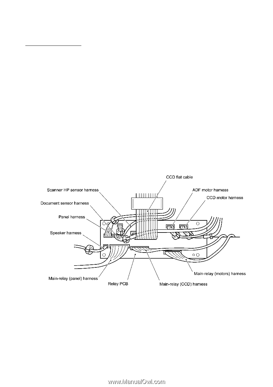
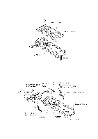
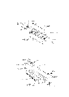
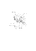
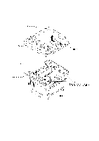
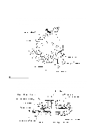
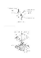
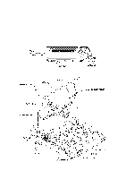
n Reassembling Notes • Take care not to mistake the upper LF roller ASSY (gray) for the lower LF roller ASSY (black). • When setting the document sensor PCB back into place, do not push it down straight, but first fit the PCB in the large latch and then fit it in the small latch (see the illustration given on page IV-13). • Be sure to route the document sensor harness through the three harness guides so that it will not interfere with the document rear sensor actuator. (See the illustration given on page IV-13.) • Reinstall the ADF motor with its connector side facing up. (See the illustration given on page IV-12.) • Reinstall the ADF side covers so that the tabs of the ADF side plates become fitted inside the ribs provided on the ADF side covers. (See the illustration given on page IV-11.) • When reinstalling the ADF side cover R, be sure to route the document sensor harness, ADF motor harness, and grounding wire between the boss and the ADF side cover R. (See the illustration given on page IV-11.) • When reinstalling the ADF unit, first set the ADF support onto rear pin "x" of the ADF unit, set the ADF unit back into place, set the other ADF support onto front pin "y," then secure those ADF supports with two screws "c." (See the illustration given on page IV-10.) • When connecting the ADF motor harness, document sensor harness, and grounding wires to the relay PCB, route them as shown below. IV - 15
-
 1
1 -
2
-
3
-
4
-
5
-
6
-
7
-
8
-
9
-
10
-
11
-
12
-
13
-
14
-
15
-
16
-
17
-
18
-
19
-
20
-
21
-
22
-
23
-
24
-
25
-
26
-
27
-
28
-
29
-
30
-
31
-
32
-
33
-
34
-
35
-
36
-
37
-
38
-
39
-
40
-
41
-
42
-
43
-
44
-
45
-
46
-
47
-
48
-
49
-
50
-
51
-
52
-
53
-
54
-
55
-
 56
56 -
 57
57 -
 58
58 -
 59
59 -
 60
60 -
 61
61 -
 62
62 -
 63
63 -
 64
64 -
 65
65 -
 66
66 -
67
-
68
-
69
-
70
-
71
-
72
-
73
-
74
-
75
-
76
-
77
-
78
-
79
-
80
-
81
-
82
-
83
-
84
-
85
-
86
-
87
-
88
-
89
-
90
-
91
-
92
-
93
-
94
-
95
-
96
-
97
-
98
-
99
-
100
-
101
-
102
-
103
-
104
-
105
-
106
-
107
-
108
-
109
-
110
-
111
-
112
-
113
-
114
-
115
-
116
-
117
-
118
-
119
-
120
-
121
-
122
-
123
-
124
-
125
-
126
-
127
-
128
-
129
-
130
-
131
-
132
-
133
-
134
-
135
-
136
-
137
-
138
-
139
-
140
-
141
-
142
-
143
-
144
-
145
-
146
-
147
-
148
-
149
-
150
-
151
-
152
-
153
-
154
-
155
-
156
-
157
-
158
-
159
-
160
-
161
-
162
-
163
-
164
-
165
-
166
-
167
-
168
-
169
-
170
-
171
-
172
-
173
-
174
-
175
-
176
-
177
-
178
-
179
-
180
-
181
-
182
-
183
-
184
-
185
-
186
-
187
-
188
-
189
-
190
-
191
-
192
-
193
-
194
-
195
-
196
-
197
-
198
-
199
-
200
-
201
-
202
-
203
-
204
-
205
-
206
-
207
-
208
-
209
-
210
-
211
-
212
-
213
-
214
-
215
-
216
-
217
-
218
-
219
-
220
-
221
-
222
-
223
-
224
-
225
-
226
-
227
-
228
-
229
-
230
-
231
-
232
-
233
-
234
-
235
-
236
-
237
-
238
-
239
-
240
-
241
-
242
-
243
-
244
-
245
-
246
-
247
-
248
-
249
-
250
-
251
-
252
-
253
-
254
-
255
-
256
-
257
-
258
-
259
-
260
-
261
-
262
-
263
-
264
-
265
-
266
-
267
-
268
-
269
-
270
-
271
-
272
-
273
-
274
-
275
-
276
-
277
-
278
-
279
-
280
-
281
-
282
-
283
-
284
-
285
-
286
 |
 |