Brother International T-8752C Instruction Manual - English - Page 79
Standard Adjustment, <for T-8421c, T-8422c And T-8722c>
 |
View all Brother International T-8752C manuals
Add to My Manuals
Save this manual to your list of manuals |
Page 79 highlights
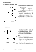
13. STANDARD ADJUSTMENT 3041M 8. Loosen the screws (10), and then remove rotary hook base cover FL (11) and FR (12). (The screws (10) is designed so that they cannot be removed from the rotary hook base cover FL (11) and FR (12) to prevent them from being lost.) 9. Loosen the set screws (13) (three each at left and right). (However, be careful not to loosen them too much, otherwise the set screws (13) will touch the inside surface of the rotary hook base and the pinion gear (14) will not be able to turn. Loosen the set screws by the minimum amount which will still allow the rotary hook to move freely.) 10. Turn the rotary hook by hand to align the rotary hook tip (15) with the middle of the needle. (Do not turn the machine pulley at this time.) 11. Tighten the set screws (13). (Tighten the three set screws (13) a little bit at a time in order so that the pinion gear (14) does not become tilted.) 12. Remove the tape that is securing the machine pulley. Color in Mark Needle bar lowest position Mark 3042M 3043M 13. Use an oil-based marker pen to color in the hollow of the needle. 14. With the needle raised, turn the machine pulley forward while pushing the needle against the rotary hook tip (15) with your finger to make a mark from the rotary hook tip (15) in the hollow of the needle. 15. Check that the distance (C) from the intersection between the mark from the rotary hook tip (15) and the center line of the needle to the top edge of the needle hole is 1-1.5 mm. * If the distance is not 1-1.5 mm, loosen the screw (5) again and adjust the height of the needle bar. * If dimension (C) has been adjusted, the highest reference line (3) on the needle bar (2) may be hidden by the bottom edge of the needle bar base (4) when the needle bar is at its lowest position, but this is not a problem. If using a thread such as polyester thread which does not easily form stable loops * If problems such as skipped stitches or upper thread breakages occur, set the above distance (C) to 0.7-1.2 mm to make it easier for the rotary hook tip (15) to catch the upper thread loop. NOTE: • When the stitch length is changed, distance (C) will also change, so re-check distance (C) at such times. • During quick reverse operation, distance (C) for the left needle will become shorter, so do not set it to less than 0.7 mm, otherwise the rotary hook tip (15) may touch the projection (D) and this could damage the rotary hook tip (15). 2262B T-8421C, 8422C, 8452C, 8722C, 8752C 70
-
 1
1 -
2
-
3
-
4
-
5
-
6
-
7
-
8
-
9
-
10
-
11
-
12
-
13
-
14
-
15
-
16
-
17
-
18
-
19
-
20
-
21
-
22
-
23
-
24
-
25
-
26
-
27
-
28
-
29
-
30
-
31
-
32
-
33
-
34
-
35
-
36
-
37
-
38
-
39
-
40
-
41
-
42
-
43
-
44
-
45
-
46
-
47
-
48
-
49
-
50
-
51
-
52
-
53
-
54
-
55
-
56
-
57
-
58
-
59
-
60
-
61
-
62
-
63
-
64
-
65
-
66
-
67
-
68
-
69
-
70
-
71
-
72
-
73
-
 74
74 -
 75
75 -
 76
76 -
 77
77 -
 78
78 -
 79
79 -
 80
80 -
 81
81 -
 82
82 -
 83
83 -
 84
84 -
85
-
86
-
87
-
88
-
89
-
90
-
91
-
92
-
93
-
94
 |
 |
