Cisco ASR1006 Configuration Guide - Page 380

Prerequisites for Frame Relay DLCI-to-ATM AAL5SNAP Bridged Interworking, Frame Relay DLCI-to-ATM

Page 380 highlights

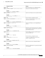
Prerequisites for Frame Relay DLCI-to-ATM AAL5SNAP Bridged Interworking Configuring MPLS Layer 2 VPNs Table 1 Range of MTUs for Different ACs AC Type Range of MTUs1 Supported ATM 64 to 9216 Gigabit Ethernet 1500 to 9216 POS 64 to 9216 Fast Ethernet 1500 to 9216 1. The MTU configured on an AC must not exceed the MTU in the core network. This ensures that the traffic is not fragmented. • The CE routers with Ethernet attachment VCs running OSPF must be configured with the ospfIfType option so that the OSPF protocol treats the underlying physical broadcast link as a P2P link. Prerequisites for Frame Relay DLCI-to-ATM AAL5SNAP Bridged Interworking Before you configure the Frame Relay Data Link Connection Identifier (DLCI)-to-ATM AAL5SNAP Bridged Interworking feature on a router, ensure that the following prerequisites are met: • Enable frame-relay switching on the Frame Relay provider edge (PE) router. • Customer edge (CE) routers must support Bridge-group Virtual Interface or Routed Bridge Encapsulation. Frame Relay DLCI-to-ATM AAL5SNAP Bridged Interworking This feature provides interoperability between the ATM attachment VC and Frame Relay attachment VC connected to different PE routers. This interworking uses the bridged encapsulation corresponding to the bridged (Ethernet) interworking mechanism. The Ethernet frames are carried through the MPLS network using Ethernet over MPLS (EoMPLS). This feature is configured only in the bridged mode and not in the routed mode. Figure 1 shows the interworking function performed in the PE routers that are connected to the ATM attachment VC and the Frame Relay attachment VC. Figure 1 Network Topology for Frame Relay DLCI-to-ATM AAL5SNAP Bridged Interworking VPI/VCI ATM Link ATM CE ATM PE Pseudowire using EoMPLS Tunnel LSP P Router P Router DLCI Frame Relay Link FR PE FR CE MPLS Network 331935 Cisco ASR 1000 Series Aggregation Services Routers Software Configuration Guide 4

  • 1
  • 2
  • 3
  • 4
  • 5
  • 6
  • 7
  • 8
  • 9
  • 10
  • 11
  • 12
  • 13
  • 14
  • 15
  • 16
  • 17
  • 18
  • 19
  • 20
  • 21
  • 22
  • 23
  • 24
  • 25
  • 26
  • 27
  • 28
  • 29
  • 30
  • 31
  • 32
  • 33
  • 34
  • 35
  • 36
  • 37
  • 38
  • 39
  • 40
  • 41
  • 42
  • 43
  • 44
  • 45
  • 46
  • 47
  • 48
  • 49
  • 50
  • 51
  • 52
  • 53
  • 54
  • 55
  • 56
  • 57
  • 58
  • 59
  • 60
  • 61
  • 62
  • 63
  • 64
  • 65
  • 66
  • 67
  • 68
  • 69
  • 70
  • 71
  • 72
  • 73
  • 74
  • 75
  • 76
  • 77
  • 78
  • 79
  • 80
  • 81
  • 82
  • 83
  • 84
  • 85
  • 86
  • 87
  • 88
  • 89
  • 90
  • 91
  • 92
  • 93
  • 94
  • 95
  • 96
  • 97
  • 98
  • 99
  • 100
  • 101
  • 102
  • 103
  • 104
  • 105
  • 106
  • 107
  • 108
  • 109
  • 110
  • 111
  • 112
  • 113
  • 114
  • 115
  • 116
  • 117
  • 118
  • 119
  • 120
  • 121
  • 122
  • 123
  • 124
  • 125
  • 126
  • 127
  • 128
  • 129
  • 130
  • 131
  • 132
  • 133
  • 134
  • 135
  • 136
  • 137
  • 138
  • 139
  • 140
  • 141
  • 142
  • 143
  • 144
  • 145
  • 146
  • 147
  • 148
  • 149
  • 150
  • 151
  • 152
  • 153
  • 154
  • 155
  • 156
  • 157
  • 158
  • 159
  • 160
  • 161
  • 162
  • 163
  • 164
  • 165
  • 166
  • 167
  • 168
  • 169
  • 170
  • 171
  • 172
  • 173
  • 174
  • 175
  • 176
  • 177
  • 178
  • 179
  • 180
  • 181
  • 182
  • 183
  • 184
  • 185
  • 186
  • 187
  • 188
  • 189
  • 190
  • 191
  • 192
  • 193
  • 194
  • 195
  • 196
  • 197
  • 198
  • 199
  • 200
  • 201
  • 202
  • 203
  • 204
  • 205
  • 206
  • 207
  • 208
  • 209
  • 210
  • 211
  • 212
  • 213
  • 214
  • 215
  • 216
  • 217
  • 218
  • 219
  • 220
  • 221
  • 222
  • 223
  • 224
  • 225
  • 226
  • 227
  • 228
  • 229
  • 230
  • 231
  • 232
  • 233
  • 234
  • 235
  • 236
  • 237
  • 238
  • 239
  • 240
  • 241
  • 242
  • 243
  • 244
  • 245
  • 246
  • 247
  • 248
  • 249
  • 250
  • 251
  • 252
  • 253
  • 254
  • 255
  • 256
  • 257
  • 258
  • 259
  • 260
  • 261
  • 262
  • 263
  • 264
  • 265
  • 266
  • 267
  • 268
  • 269
  • 270
  • 271
  • 272
  • 273
  • 274
  • 275
  • 276
  • 277
  • 278
  • 279
  • 280
  • 281
  • 282
  • 283
  • 284
  • 285
  • 286
  • 287
  • 288
  • 289
  • 290
  • 291
  • 292
  • 293
  • 294
  • 295
  • 296
  • 297
  • 298
  • 299
  • 300
  • 301
  • 302
  • 303
  • 304
  • 305
  • 306
  • 307
  • 308
  • 309
  • 310
  • 311
  • 312
  • 313
  • 314
  • 315
  • 316
  • 317
  • 318
  • 319
  • 320
  • 321
  • 322
  • 323
  • 324
  • 325
  • 326
  • 327
  • 328
  • 329
  • 330
  • 331
  • 332
  • 333
  • 334
  • 335
  • 336
  • 337
  • 338
  • 339
  • 340
  • 341
  • 342
  • 343
  • 344
  • 345
  • 346
  • 347
  • 348
  • 349
  • 350
  • 351
  • 352
  • 353
  • 354
  • 355
  • 356
  • 357
  • 358
  • 359
  • 360
  • 361
  • 362
  • 363
  • 364
  • 365
  • 366
  • 367
  • 368
  • 369
  • 370
  • 371
  • 372
  • 373
  • 374
  • 375
  • 376
  • 377
  • 378
  • 379
  • 380
  • 381
  • 382
  • 383
  • 384
  • 385
  • 386
  • 387
  • 388
  • 389
  • 390
  • 391
  • 392
  • 393
  • 394
  • 395
  • 396
  • 397
  • 398
  • 399
  • 400
  • 401
  • 402
  • 403
  • 404
  • 405
  • 406
  • 407
  • 408
  • 409
  • 410
  • 411
  • 412
  • 413
  • 414
  • 415
  • 416
  • 417
  • 418
  • 419
  • 420
  • 421
  • 422
  • 423
  • 424
  • 425
  • 426
  • 427
  • 428
  • 429
  • 430
  • 431
  • 432
  • 433
  • 434
  • 435
  • 436
  • 437
  • 438
  • 439
  • 440
  • 441
  • 442
  • 443
  • 444
  • 445
  • 446
  • 447
  • 448
  • 449
  • 450
  • 451
  • 452
  • 453
  • 454
  • 455
  • 456
  • 457
  • 458
  • 459
  • 460
  • 461
  • 462

Configuring MPLS Layer 2 VPNs
Prerequisites for Frame Relay DLCI-to-ATM AAL5SNAP Bridged Interworking
4
Cisco ASR 1000 Series Aggregation Services Routers Software Configuration Guide
The CE routers with Ethernet attachment VCs running OSPF must be configured with the
ospfIfType
option so that the OSPF protocol treats the underlying physical broadcast link as a P2P link.
Prerequisites for Frame Relay DLCI-to-ATM AAL5SNAP Bridged
Interworking
Before you configure the Frame Relay Data Link Connection Identifier (DLCI)-to-ATM AAL5SNAP
Bridged Interworking feature on a router, ensure that the following prerequisites are met:
Enable frame-relay switching on the Frame Relay provider edge (PE) router.
Customer edge (CE) routers must support Bridge-group Virtual Interface or Routed Bridge
Encapsulation.
Frame Relay DLCI-to-ATM AAL5SNAP Bridged Interworking
This feature provides interoperability between the ATM attachment VC and Frame Relay attachment VC
connected to different PE routers. This interworking uses the bridged encapsulation corresponding to the
bridged (Ethernet) interworking mechanism. The Ethernet frames are carried through the MPLS network
using Ethernet over MPLS (EoMPLS). This feature is configured only in the bridged mode and not in
the routed mode.
Figure 1
shows the interworking function performed in the PE routers that are connected to the ATM
attachment VC and the Frame Relay attachment VC.
Figure 1
Network Topology for Frame Relay DLCI-to-ATM AAL5SNAP Bridged Interworking
Table 1
Range of MTUs for Different ACs
AC Type
Range of MTUs
1
Supported
1.
The MTU configured on an AC must not exceed the MTU in the core network. This ensures that the traffic is not fragmented.
ATM
64 to 9216
Gigabit Ethernet
1500 to 9216
POS
64 to 9216
Fast Ethernet
1500 to 9216
331935
DLCI
VPI/VCI
ATM Link
Pseudowire using EoMPLS
P Router
P Router
FR PE
ATM PE
ATM CE
MPLS Network
FR CE
Tunnel LSP
Frame Relay
Link