Cisco SFS-7012 User Guide - Page 40
Installation Tasks, Mounting Kit, Mark the Rack, Install the Rails in the Rack
 |
View all Cisco SFS-7012 manuals
Add to My Manuals
Save this manual to your list of manuals |
Page 40 highlights
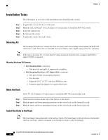
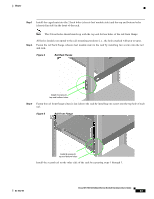
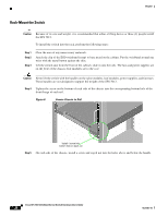
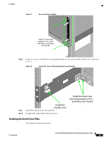
Chapter Installation Tasks The following is an overview of the installation tasks detailed in this section: Step 1 Step 2 Step 3 Step 4 Step 5 If applicable, remove the doors of the rack. Mark the rack, allowing 7 U (12.25 inches) of vertical space to install the SFS 7012 switch. Install the support rails. Rack mount the switch. If applicable, replace the rack's doors. Mounting Kit The mounting kit hardware contains all of the necessary parts for installing and mounting the SFS 7012 switch into a rack. These kits are intended for use in cabinets with a depth ranging from 28 - 34 inches. Note If the rack is less than 28", or more than 34" deep, instead of using the rails, a support shelf able to support 100 lbs is required. Mounting Hardware Kit Contents: • Kit Mounting Rails containing: - One pair (left and right) of support rail assemblies • Kit Mounting Hardware 3/8" Square Hole containing: - One pair of lower rear mounting brackets - Two heyclips - Eighteen 10/32" x 0.375" pan-head Phillips screws - Fourteen caged nut adapters for square-holed racks Mark the Rack Allow 7U (12.25 inches) of vertical space to install the SFS 7012 switch in the rack. Step 1 Step 2 Step 3 Determine the location on the rack of the bottom of the switch. Mark the upper and lower mounting positions on the vertical rails on the front of the rack. Mark the upper and lower mounting positions on the vertical rails on the back of the rack. Install the Rails in the Rack Note The front flange (chassis fan side) of the rail has 3 holes. The back flange of the rail (chassis leaf module side) has two holes, which correspond to the bottom two holes on the front flange. Cisco SFS 7012 InfiniBand Server Switch Hardware Users Guide 22 OL-8787-04
-
 1
1 -
2
-
3
-
4
-
5
-
6
-
7
-
8
-
9
-
10
-
11
-
12
-
13
-
14
-
15
-
16
-
17
-
18
-
19
-
20
-
21
-
22
-
23
-
24
-
25
-
26
-
27
-
28
-
29
-
30
-
31
-
32
-
33
-
34
-
 35
35 -
 36
36 -
 37
37 -
 38
38 -
 39
39 -
 40
40 -
 41
41 -
 42
42 -
 43
43 -
 44
44 -
 45
45 -
46
-
47
-
48
-
49
-
50
-
51
-
52
-
53
-
54
-
55
-
56
-
57
-
58
-
59
-
60
-
61
-
62
-
63
-
64
-
65
-
66
-
67
-
68
-
69
-
70
-
71
-
72
-
73
-
74
-
75
-
76
-
77
-
78
-
79
-
80
-
81
-
82
-
83
-
84
-
85
-
86
-
87
-
88
-
89
-
90
-
91
-
92
-
93
-
94
-
95
-
96
-
97
-
98
-
99
-
100
-
101
-
102
-
103
-
104
-
105
-
106
-
107
-
108
-
109
-
110
-
111
-
112
-
113
-
114
-
115
-
116
 |
 |
