Cisco SFS-7012 User Guide - Page 45
Connect Equipment to the Ports and Power On the System, Leaf 1
 |
View all Cisco SFS-7012 manuals
Add to My Manuals
Save this manual to your list of manuals |
Page 45 highlights
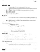
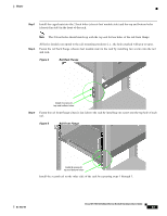
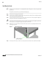
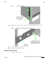
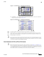
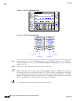
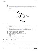
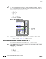
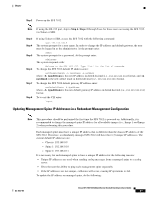
Chapter Figure 2-9 SFS 7012 Chassis - Spine Module Slot Numbering b. Leaf Modules- Leaf modules should be populated beginning with slot 1, then slot 2, then slots 3 through 12 respectively. Refer to Figure 2-10: Figure 2-10 SFS 7012 Chassis - Leaf Module Slot Numbering Leaf 11 Leaf 12 Leaf 9 Leaf 10 Leaf 7 Leaf 5 Leaf 3 Leaf 1 Leaf 8 Leaf 6 Leaf 4 Leaf 2 Step 2 Step 3 Step 4 To install a module or filler, hold it so that the ejector handles are on the bottom. Pull the handles out to extend them. Slide the module into the appropriate slot of the chassis until it makes contact with the backplane. As the module seats in the chassis, the handles will begin to close. Push the handles in to fully close. Note Be sure that all cards are fully inserted in their respective chassis slots, and that the handles are in the locked position. This prevents accidental removal, provides proper grounding for the system, and helps to seat the bus connectors in the backplane receptacles. Connect Equipment to the Ports and Power On the System Note Before performing the tasks in this section, take a few minutes to review Figure 2-11 and Figure 2-12 below. It is important to understand the slot numbering for the leaf modules and spine modules (and the corresponding spine RJ-45 ports). It is also important to understand the slot numbering for the fans and power supplies (and the corresponding AC power inlets for the power supplies). OL-8787-04 Cisco SFS 7012 InfiniBand Server Switch Hardware Users Guide 27
-
 1
1 -
2
-
3
-
4
-
5
-
6
-
7
-
8
-
9
-
10
-
11
-
12
-
13
-
14
-
15
-
16
-
17
-
18
-
19
-
20
-
21
-
22
-
23
-
24
-
25
-
26
-
27
-
28
-
29
-
30
-
31
-
32
-
33
-
34
-
35
-
36
-
37
-
38
-
39
-
 40
40 -
 41
41 -
 42
42 -
 43
43 -
 44
44 -
 45
45 -
 46
46 -
 47
47 -
 48
48 -
 49
49 -
 50
50 -
51
-
52
-
53
-
54
-
55
-
56
-
57
-
58
-
59
-
60
-
61
-
62
-
63
-
64
-
65
-
66
-
67
-
68
-
69
-
70
-
71
-
72
-
73
-
74
-
75
-
76
-
77
-
78
-
79
-
80
-
81
-
82
-
83
-
84
-
85
-
86
-
87
-
88
-
89
-
90
-
91
-
92
-
93
-
94
-
95
-
96
-
97
-
98
-
99
-
100
-
101
-
102
-
103
-
104
-
105
-
106
-
107
-
108
-
109
-
110
-
111
-
112
-
113
-
114
-
115
-
116
 |
 |
