Cisco SFS-7012 User Guide - Page 41
Rail Back Flange, Step 1
 |
View all Cisco SFS-7012 manuals
Add to My Manuals
Save this manual to your list of manuals |
Page 41 highlights
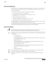
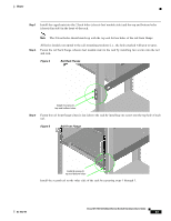
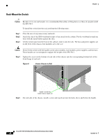
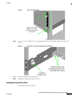
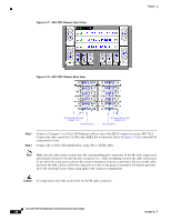
Chapter Step 1 Install the caged nuts into the 2 back holes (chassis leaf module side) and the top and bottom holes (chassis fan side) in the front of the rack. Note The 2 front holes should match up with the top and bottom holes of the rail front flange. Step 2 All holes should correspond to the rail mounting positions (i.e., the holes marked with pen or tape). Fasten the rail back flange (chassis leaf module side) to the rack by installing two screws into the rail and rack. Figure 4 Rail Back Flange Install 2 screws to top and bottom holes Step 3 Fasten the rail front flange (chassis fan side) to the rack by installing one screw into the top hole of each rail. Figure 5 Rail Front Flange Install 2 screws to top and bottom holes Install the second rail on the other side of the rack by repeating steps 1 through 3. OL-8787-04 Cisco SFS 7012 InfiniBand Server Switch Hardware Users Guide 23
-
 1
1 -
2
-
3
-
4
-
5
-
6
-
7
-
8
-
9
-
10
-
11
-
12
-
13
-
14
-
15
-
16
-
17
-
18
-
19
-
20
-
21
-
22
-
23
-
24
-
25
-
26
-
27
-
28
-
29
-
30
-
31
-
32
-
33
-
34
-
35
-
 36
36 -
 37
37 -
 38
38 -
 39
39 -
 40
40 -
 41
41 -
 42
42 -
 43
43 -
 44
44 -
 45
45 -
 46
46 -
47
-
48
-
49
-
50
-
51
-
52
-
53
-
54
-
55
-
56
-
57
-
58
-
59
-
60
-
61
-
62
-
63
-
64
-
65
-
66
-
67
-
68
-
69
-
70
-
71
-
72
-
73
-
74
-
75
-
76
-
77
-
78
-
79
-
80
-
81
-
82
-
83
-
84
-
85
-
86
-
87
-
88
-
89
-
90
-
91
-
92
-
93
-
94
-
95
-
96
-
97
-
98
-
99
-
100
-
101
-
102
-
103
-
104
-
105
-
106
-
107
-
108
-
109
-
110
-
111
-
112
-
113
-
114
-
115
-
116
 |
 |
