Cisco WS-C2950T-24 Hardware Installation Guide - Page 165
Installing and Removing DRAM DIMMs, Locating and Orienting DRAM DIMM
 |
View all Cisco WS-C2950T-24 manuals
Add to My Manuals
Save this manual to your list of manuals |
Page 165 highlights
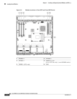
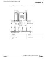
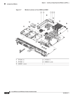
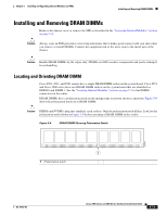
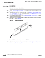
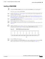
Chapter 5 Installing and Upgrading Internal Modules and FRUs Installing and Removing DRAM DIMMs Installing and Removing DRAM DIMMs Remove the chassis cover or remove the SPE as described in the "Accessing Internal Modules" section on page 5-4. Caution Always wear an ESD-preventive wrist strap and ensure that it makes good contact with your skin when you remove or install DIMMs. Connect the equipment end of the wrist strap to the metal part of the chassis. Caution Handle DRAM DIMMs by the edges only. DIMMs are ESD-sensitive components and can be damaged by mishandling. Locating and Orienting DRAM DIMM Cisco 2901, 2911, and 2921 routers have a single DRAM DIMM socket on the system board. Cisco 2951 and Cisco 3900 series have two DRAM DIMM sockets on the system board that are identified as DIMM 0 and DIMM 1. See the "Locating Internal Modules" section on page 5-7 to find DIMM connectors on the router. DRAM DIMMs have a polarization notch on the mating edge to prevent incorrect insertion. Figure 5-8 shows the polarization notch on a DRAM DIMM. Caution DIMMs and PVDM3s plug into similarly sized sockets. Only the polarization notch differs. Look for the polarization notch shown in Figure 5-8 before inserting a DRAM DIMM in the socket. Figure 5-8 DRAM DIMM Showing Polarization Notch 250944 1 1 Polarization notch OL-18712-03 Cisco 2900 Series and 3900 Series Hardware Installation Guide 5-13
-
 1
1 -
2
-
3
-
4
-
5
-
6
-
7
-
8
-
9
-
10
-
11
-
12
-
13
-
14
-
15
-
16
-
17
-
18
-
19
-
20
-
21
-
22
-
23
-
24
-
25
-
26
-
27
-
28
-
29
-
30
-
31
-
32
-
33
-
34
-
35
-
36
-
37
-
38
-
39
-
40
-
41
-
42
-
43
-
44
-
45
-
46
-
47
-
48
-
49
-
50
-
51
-
52
-
53
-
54
-
55
-
56
-
57
-
58
-
59
-
60
-
61
-
62
-
63
-
64
-
65
-
66
-
67
-
68
-
69
-
70
-
71
-
72
-
73
-
74
-
75
-
76
-
77
-
78
-
79
-
80
-
81
-
82
-
83
-
84
-
85
-
86
-
87
-
88
-
89
-
90
-
91
-
92
-
93
-
94
-
95
-
96
-
97
-
98
-
99
-
100
-
101
-
102
-
103
-
104
-
105
-
106
-
107
-
108
-
109
-
110
-
111
-
112
-
113
-
114
-
115
-
116
-
117
-
118
-
119
-
120
-
121
-
122
-
123
-
124
-
125
-
126
-
127
-
128
-
129
-
130
-
131
-
132
-
133
-
134
-
135
-
136
-
137
-
138
-
139
-
140
-
141
-
142
-
143
-
144
-
145
-
146
-
147
-
148
-
149
-
150
-
151
-
152
-
153
-
154
-
155
-
156
-
157
-
158
-
159
-
 160
160 -
 161
161 -
 162
162 -
 163
163 -
 164
164 -
 165
165 -
 166
166 -
 167
167 -
 168
168 -
 169
169 -
 170
170 -
171
-
172
-
173
-
174
-
175
-
176
-
177
-
178
-
179
-
180
-
181
-
182
-
183
-
184
-
185
-
186
-
187
-
188
-
189
-
190
-
191
-
192
-
193
-
194
-
195
-
196
-
197
-
198
-
199
-
200
-
201
-
202
-
203
-
204
-
205
-
206
-
207
-
208
-
209
-
210
-
211
-
212
-
213
-
214
-
215
-
216
-
217
-
218
-
219
-
220
 |
 |
