Cisco WS-C2950T-24 Hardware Installation Guide - Page 173
PVDM3 Location and Orientation, Removing a PVDM3, Router, Motherboard, Number of Supported PVDM3
 |
View all Cisco WS-C2950T-24 manuals
Add to My Manuals
Save this manual to your list of manuals |
Page 173 highlights
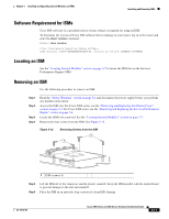
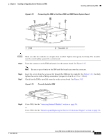
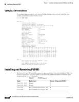
Chapter 5 Installing and Upgrading Internal Modules and FRUs Installing and Removing PVDM3 Router Cisco 3925E Cisco 3945E Table 5-1 PVDM3 Support (continued) Motherboard Services Performance Engine 200 Services Performance Engine 250 Number of Supported PVDM3 3 3 PVDMs must be used in an homogeneous fashion. In other words, do not mix PVDM2s with PVDM3s in the same router. PVDM slot numbering is defined in the "Locating Internal Modules" section on page 5-7. When using only one PVDM, ensure the module is installed in slot0. PVDM2s must be installed in a PVDM II adapter for use in the PVDM3 slot on Cisco 2900 series and Cisco 3900 series ISRs. See the "Installing and Removing PVDM2s" section on page 5-23. Caution When you remove or install PVDMs, always wear an ESD-preventive wrist strap, and ensure that it makes good contact with your skin. Connect the equipment end of the wrist strap to the metal part of the chassis. Caution Handle PVDMs by the edges only. PVDMs are ESD-sensitive components and can be damaged by mishandling. PVDM3 Location and Orientation The PVDM3 connectors are located on the motherboard and are identified as PVDM3 0 through 3. See the "Locating Internal Modules" section on page 5-7 for locations. PVDM3s have a polarization notch on the mating edge to prevent incorrect insertion. Caution PVDM3s and DIMMs plug into similarly sized connectors. Only the polarization notch differs. Be sure that you are inserting the PVDM3 into the PVDM3 connector. See Figure 5-10 for an example of the DIMM polarization notch. Removing a PVDM3 To remove a PVDM3 from the motherboard, follow these steps: Step 1 Step 2 Step 3 Read the "Safety Warnings" section on page 5-2 section and disconnect the power supply before you perform any module replacement. Locate the PVDM3 on the motherboard. See the "Locating Internal Modules" section on page 5-7. Pull the PVDM3 retaining clips away from the PVDM3 at both ends, and then lift the PVDM3 straight up from the connector. See Figure 5-16. OL-18712-03 Cisco 2900 Series and 3900 Series Hardware Installation Guide 5-21
-
 1
1 -
2
-
3
-
4
-
5
-
6
-
7
-
8
-
9
-
10
-
11
-
12
-
13
-
14
-
15
-
16
-
17
-
18
-
19
-
20
-
21
-
22
-
23
-
24
-
25
-
26
-
27
-
28
-
29
-
30
-
31
-
32
-
33
-
34
-
35
-
36
-
37
-
38
-
39
-
40
-
41
-
42
-
43
-
44
-
45
-
46
-
47
-
48
-
49
-
50
-
51
-
52
-
53
-
54
-
55
-
56
-
57
-
58
-
59
-
60
-
61
-
62
-
63
-
64
-
65
-
66
-
67
-
68
-
69
-
70
-
71
-
72
-
73
-
74
-
75
-
76
-
77
-
78
-
79
-
80
-
81
-
82
-
83
-
84
-
85
-
86
-
87
-
88
-
89
-
90
-
91
-
92
-
93
-
94
-
95
-
96
-
97
-
98
-
99
-
100
-
101
-
102
-
103
-
104
-
105
-
106
-
107
-
108
-
109
-
110
-
111
-
112
-
113
-
114
-
115
-
116
-
117
-
118
-
119
-
120
-
121
-
122
-
123
-
124
-
125
-
126
-
127
-
128
-
129
-
130
-
131
-
132
-
133
-
134
-
135
-
136
-
137
-
138
-
139
-
140
-
141
-
142
-
143
-
144
-
145
-
146
-
147
-
148
-
149
-
150
-
151
-
152
-
153
-
154
-
155
-
156
-
157
-
158
-
159
-
160
-
161
-
162
-
163
-
164
-
165
-
166
-
167
-
 168
168 -
 169
169 -
 170
170 -
 171
171 -
 172
172 -
 173
173 -
 174
174 -
 175
175 -
 176
176 -
 177
177 -
 178
178 -
179
-
180
-
181
-
182
-
183
-
184
-
185
-
186
-
187
-
188
-
189
-
190
-
191
-
192
-
193
-
194
-
195
-
196
-
197
-
198
-
199
-
200
-
201
-
202
-
203
-
204
-
205
-
206
-
207
-
208
-
209
-
210
-
211
-
212
-
213
-
214
-
215
-
216
-
217
-
218
-
219
-
220
 |
 |
