Cisco WS-C2950T-24 Hardware Installation Guide - Page 189
Replacing the Power Supply on the Cisco 2921 and Cisco 2951 Routers, Step 1
 |
View all Cisco WS-C2950T-24 manuals
Add to My Manuals
Save this manual to your list of manuals |
Page 189 highlights
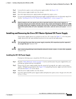
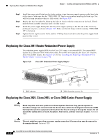
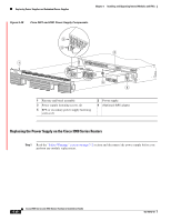
Chapter 5 Installing and Upgrading Internal Modules and FRUs Replacing Power Supplies and Redundant Power Supplies Several power supply options are available for the Cisco 2921, 2951, and 3900 series routers. See Table 5-2. All of the power supply and RPS options have a similar modular form factor, with no cabling, for easy removal and replacement. If an RPS is attached, the power supply may be hot-swapped. Note The 3900 series routers do not use an external RPS, and instead use an optional secondary internal power supply. Note Read this entire procedure and have all of your tools and the replacement power supply ready before performing a hot-swap. The hot-swap procedure requires removal of the cooling fans. You have only a few minutes to replace the fans before the router powers off, because the router has reached the upper temperature limits. Replacing the Power Supply on the Cisco 2921 and Cisco 2951 Routers Step 1 Step 2 Step 3 Step 4 Step 5 Step 6 Read the "Safety Warnings" section on page 5-2 section and disconnect the power supply before you perform any module replacement. Remove the fan tray and bezel assembly by pulling the fan tray and bezel assembly straight out. See Figure 5-30. Loosen the two captive screws on the power supply module. See Figure 5-30. Pull on the two captive power supply fastening screws to leverage the power supply from its connector, and then slide the power supply module out of the chassis. Insert the replacement power supply module, and tighten the captive screws. Reinstall the fan tray and bezel assemblies. OL-18712-03 Cisco 2900 Series and 3900 Series Hardware Installation Guide 5-37
-
 1
1 -
2
-
3
-
4
-
5
-
6
-
7
-
8
-
9
-
10
-
11
-
12
-
13
-
14
-
15
-
16
-
17
-
18
-
19
-
20
-
21
-
22
-
23
-
24
-
25
-
26
-
27
-
28
-
29
-
30
-
31
-
32
-
33
-
34
-
35
-
36
-
37
-
38
-
39
-
40
-
41
-
42
-
43
-
44
-
45
-
46
-
47
-
48
-
49
-
50
-
51
-
52
-
53
-
54
-
55
-
56
-
57
-
58
-
59
-
60
-
61
-
62
-
63
-
64
-
65
-
66
-
67
-
68
-
69
-
70
-
71
-
72
-
73
-
74
-
75
-
76
-
77
-
78
-
79
-
80
-
81
-
82
-
83
-
84
-
85
-
86
-
87
-
88
-
89
-
90
-
91
-
92
-
93
-
94
-
95
-
96
-
97
-
98
-
99
-
100
-
101
-
102
-
103
-
104
-
105
-
106
-
107
-
108
-
109
-
110
-
111
-
112
-
113
-
114
-
115
-
116
-
117
-
118
-
119
-
120
-
121
-
122
-
123
-
124
-
125
-
126
-
127
-
128
-
129
-
130
-
131
-
132
-
133
-
134
-
135
-
136
-
137
-
138
-
139
-
140
-
141
-
142
-
143
-
144
-
145
-
146
-
147
-
148
-
149
-
150
-
151
-
152
-
153
-
154
-
155
-
156
-
157
-
158
-
159
-
160
-
161
-
162
-
163
-
164
-
165
-
166
-
167
-
168
-
169
-
170
-
171
-
172
-
173
-
174
-
175
-
176
-
177
-
178
-
179
-
180
-
181
-
182
-
183
-
 184
184 -
 185
185 -
 186
186 -
 187
187 -
 188
188 -
 189
189 -
 190
190 -
 191
191 -
 192
192 -
 193
193 -
 194
194 -
195
-
196
-
197
-
198
-
199
-
200
-
201
-
202
-
203
-
204
-
205
-
206
-
207
-
208
-
209
-
210
-
211
-
212
-
213
-
214
-
215
-
216
-
217
-
218
-
219
-
220
 |
 |
