Cisco WS-C2950T-24 Hardware Installation Guide - Page 22
Chassis Views, Cisco 2901 Chassis
 |
View all Cisco WS-C2950T-24 manuals
Add to My Manuals
Save this manual to your list of manuals |
Page 22 highlights
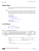
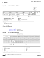
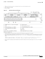
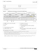
Chassis Views Chapter 1 Overview of the Routers Chassis Views This section contains views of the front and back panels of the Cisco 2900 series and Cisco 3900 series routers, showing locations of the power and signal interfaces, module slots, status indicators, and chassis identification labels. Note Routers support the following slot types: Service Modules (SMs), Enhanced High-Speed Interface Card (EHWICs), high-speed WAN interface cards (HWICs), voice WAN interface cards (VWICs), WAN interface cards (WICs), Internal Services Modules (ISMs), and packet voice DSP modules (PVDM3s). However, some router models do not support all of these media types. See the router model descriptions for more information. Cisco 2900 Series ISRs • Cisco 2901 Chassis, page 1-2 • Cisco 2911 Chassis, page 1-4 • Cisco 2921 and Cisco 2951 Chassis, page 1-6 Cisco 3900 Series ISRs • Cisco 3900 Series Chassis, page 1-8 Cisco 2901 Chassis Figure 1-1- Front panel Figure 1-2 on page 1-3- Back panel Figure 1-3 on page 1-4- Back panel LEDs Figure 1-1 Front Panel of the Cisco 2901 Router Cisco 2900 Series SYS ACT POE 1 2 3 45 6 1 SYS1 3 POE3 5 On/off switch 2 ACT2 4 AC OK4 (only on AC PS, not AC-POE PS) 6 AC power connector 1. System 2. Activity 3. POE = power over Ethernet. 4. LED goes off if the AC power fails or is disconnected. It does not go on and off with the power switch. 250957 Cisco 2900 Series and 3900 Series Hardware Installation Guide 1-2 OL-18712-02
-
 1
1 -
2
-
3
-
4
-
5
-
6
-
7
-
8
-
9
-
10
-
11
-
12
-
13
-
14
-
15
-
16
-
 17
17 -
 18
18 -
 19
19 -
 20
20 -
 21
21 -
 22
22 -
 23
23 -
 24
24 -
 25
25 -
 26
26 -
 27
27 -
28
-
29
-
30
-
31
-
32
-
33
-
34
-
35
-
36
-
37
-
38
-
39
-
40
-
41
-
42
-
43
-
44
-
45
-
46
-
47
-
48
-
49
-
50
-
51
-
52
-
53
-
54
-
55
-
56
-
57
-
58
-
59
-
60
-
61
-
62
-
63
-
64
-
65
-
66
-
67
-
68
-
69
-
70
-
71
-
72
-
73
-
74
-
75
-
76
-
77
-
78
-
79
-
80
-
81
-
82
-
83
-
84
-
85
-
86
-
87
-
88
-
89
-
90
-
91
-
92
-
93
-
94
-
95
-
96
-
97
-
98
-
99
-
100
-
101
-
102
-
103
-
104
-
105
-
106
-
107
-
108
-
109
-
110
-
111
-
112
-
113
-
114
-
115
-
116
-
117
-
118
-
119
-
120
-
121
-
122
-
123
-
124
-
125
-
126
-
127
-
128
-
129
-
130
-
131
-
132
-
133
-
134
-
135
-
136
-
137
-
138
-
139
-
140
-
141
-
142
-
143
-
144
-
145
-
146
-
147
-
148
-
149
-
150
-
151
-
152
-
153
-
154
-
155
-
156
-
157
-
158
-
159
-
160
-
161
-
162
-
163
-
164
-
165
-
166
-
167
-
168
-
169
-
170
-
171
-
172
-
173
-
174
-
175
-
176
-
177
-
178
-
179
-
180
-
181
-
182
-
183
-
184
-
185
-
186
-
187
-
188
-
189
-
190
-
191
-
192
-
193
-
194
-
195
-
196
-
197
-
198
-
199
-
200
-
201
-
202
-
203
-
204
-
205
-
206
-
207
-
208
-
209
-
210
-
211
-
212
-
213
-
214
-
215
-
216
-
217
-
218
-
219
-
220
 |
 |
