Cisco WS-C2950T-24 Hardware Installation Guide - Page 175
Installing and Removing PVDM2s
 |
View all Cisco WS-C2950T-24 manuals
Add to My Manuals
Save this manual to your list of manuals |
Page 175 highlights
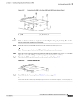
Chapter 5 Installing and Upgrading Internal Modules and FRUs Figure 5-17 Installing a PVDM3 2 Installing and Removing PVDM2s 1 2 103467 1 Insert PVDM3 into connector 2 Snap retaining clips into place Step 4 Step 5 Insert the PVDM3 firmly into the connector until seated. Replace the chassis cover. For Cisco 2900 series ISRs replace the cover. See the "Removing and Replacing the Chassis Cover" section on page 5-4. For Cisco 3900 series ISRs replace the SPE. See the "Removing and Replacing the Services Performance Engine" section on page 5-6. Installing and Removing PVDM2s A PVDM adapter must be used to insert a PVDM2 into the PVDM3 slot. The PVDM adapter is a small circuit board with connectors and clips that securely mount the PVDM2 into the PVDM3 slot. The clips are on the side of the adapter and require physical manipulation to secure the module in place. The following video clip shows how to install and remove a PVDM2 from the adapter. http://cisco.com/en/US/docs/routers/access/2900/videos/PVDM/PVDM_Adapter.swf • PVDM Adapter-Figure 5-18 on page 5-24 • Clips and Guide Post-Figure 5-19 on page 5-25 • Clips Open-Figure 5-20 on page 5-26 • Clips Closed-Figure 5-21 on page 5-26 OL-18712-03 Cisco 2900 Series and 3900 Series Hardware Installation Guide 5-23
-
 1
1 -
2
-
3
-
4
-
5
-
6
-
7
-
8
-
9
-
10
-
11
-
12
-
13
-
14
-
15
-
16
-
17
-
18
-
19
-
20
-
21
-
22
-
23
-
24
-
25
-
26
-
27
-
28
-
29
-
30
-
31
-
32
-
33
-
34
-
35
-
36
-
37
-
38
-
39
-
40
-
41
-
42
-
43
-
44
-
45
-
46
-
47
-
48
-
49
-
50
-
51
-
52
-
53
-
54
-
55
-
56
-
57
-
58
-
59
-
60
-
61
-
62
-
63
-
64
-
65
-
66
-
67
-
68
-
69
-
70
-
71
-
72
-
73
-
74
-
75
-
76
-
77
-
78
-
79
-
80
-
81
-
82
-
83
-
84
-
85
-
86
-
87
-
88
-
89
-
90
-
91
-
92
-
93
-
94
-
95
-
96
-
97
-
98
-
99
-
100
-
101
-
102
-
103
-
104
-
105
-
106
-
107
-
108
-
109
-
110
-
111
-
112
-
113
-
114
-
115
-
116
-
117
-
118
-
119
-
120
-
121
-
122
-
123
-
124
-
125
-
126
-
127
-
128
-
129
-
130
-
131
-
132
-
133
-
134
-
135
-
136
-
137
-
138
-
139
-
140
-
141
-
142
-
143
-
144
-
145
-
146
-
147
-
148
-
149
-
150
-
151
-
152
-
153
-
154
-
155
-
156
-
157
-
158
-
159
-
160
-
161
-
162
-
163
-
164
-
165
-
166
-
167
-
168
-
169
-
 170
170 -
 171
171 -
 172
172 -
 173
173 -
 174
174 -
 175
175 -
 176
176 -
 177
177 -
 178
178 -
 179
179 -
 180
180 -
181
-
182
-
183
-
184
-
185
-
186
-
187
-
188
-
189
-
190
-
191
-
192
-
193
-
194
-
195
-
196
-
197
-
198
-
199
-
200
-
201
-
202
-
203
-
204
-
205
-
206
-
207
-
208
-
209
-
210
-
211
-
212
-
213
-
214
-
215
-
216
-
217
-
218
-
219
-
220
 |
 |
