Cisco WS-C2950T-24 Hardware Installation Guide - Page 92
Mounting the Router in a Rack
 |
View all Cisco WS-C2950T-24 manuals
Add to My Manuals
Save this manual to your list of manuals |
Page 92 highlights
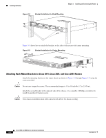
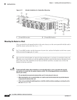
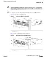
Installing the Router Chapter 3 Installing and Connecting the Router Figure 3-11 1 Bracket Installation for Center-Rear Mounting 2 250927 DNOENTOWTORREKMOOPVEERDATUIROINNG DNOENTOWTORREKMOOPVEERDATUIROINNG 1 23-inch EIA brackets 2 1 2 19-inch EIA brackets Mounting the Router in a Rack After you attach the rack-mount brackets to the router chassis, use the screws provided with the rack to install the chassis in the rack. (See Figure 3-12.) Tip For 23-inch SBC brackets start the lower pair of screws first, and rest the brackets on the lower screws while you insert the upper pair of screws. Tip The screw slots in the brackets are spaced to line up with every second pair of screw holes in the rack. When the correct screw holes are used, the small threaded holes in the brackets line up with unused screw holes in the rack. If the small holes do not line up with the rack holes, you must raise or lower the brackets to the next rack hole. Warning To prevent bodily injury when mounting or servicing this unit in a rack, you must take special precautions to ensure that the system remains stable. The following guidelines are provided to ensure your safety: • This unit should be mounted at the bottom of the rack if it is the only unit in the rack. • When mounting this unit in a partially filled rack, load the rack from the bottom to the top with the heaviest component at the bottom of the rack. • If the rack is provided with stabilizing devices, install the stabilizers before mounting or servicing the unit in the rack. Statement 1006 3-10 Cisco 2900 and 3900 Series Hardware Installation OL-18712-01
-
 1
1 -
2
-
3
-
4
-
5
-
6
-
7
-
8
-
9
-
10
-
11
-
12
-
13
-
14
-
15
-
16
-
17
-
18
-
19
-
20
-
21
-
22
-
23
-
24
-
25
-
26
-
27
-
28
-
29
-
30
-
31
-
32
-
33
-
34
-
35
-
36
-
37
-
38
-
39
-
40
-
41
-
42
-
43
-
44
-
45
-
46
-
47
-
48
-
49
-
50
-
51
-
52
-
53
-
54
-
55
-
56
-
57
-
58
-
59
-
60
-
61
-
62
-
63
-
64
-
65
-
66
-
67
-
68
-
69
-
70
-
71
-
72
-
73
-
74
-
75
-
76
-
77
-
78
-
79
-
80
-
81
-
82
-
83
-
84
-
85
-
86
-
 87
87 -
 88
88 -
 89
89 -
 90
90 -
 91
91 -
 92
92 -
 93
93 -
 94
94 -
 95
95 -
 96
96 -
 97
97 -
98
-
99
-
100
-
101
-
102
-
103
-
104
-
105
-
106
-
107
-
108
-
109
-
110
-
111
-
112
-
113
-
114
-
115
-
116
-
117
-
118
-
119
-
120
-
121
-
122
-
123
-
124
-
125
-
126
-
127
-
128
-
129
-
130
-
131
-
132
-
133
-
134
-
135
-
136
-
137
-
138
-
139
-
140
-
141
-
142
-
143
-
144
-
145
-
146
-
147
-
148
-
149
-
150
-
151
-
152
-
153
-
154
-
155
-
156
-
157
-
158
-
159
-
160
-
161
-
162
-
163
-
164
-
165
-
166
-
167
-
168
-
169
-
170
-
171
-
172
-
173
-
174
-
175
-
176
-
177
-
178
-
179
-
180
-
181
-
182
-
183
-
184
-
185
-
186
-
187
-
188
-
189
-
190
-
191
-
192
-
193
-
194
-
195
-
196
-
197
-
198
-
199
-
200
-
201
-
202
-
203
-
204
-
205
-
206
-
207
-
208
-
209
-
210
-
211
-
212
-
213
-
214
-
215
-
216
-
217
-
218
-
219
-
220
 |
 |
