Cisco WS-C2950T-24 Hardware Installation Guide - Page 186
Removing the 2911 DC Power Supply, Installing the Cisco 2911 Router Power Supply Blank
 |
View all Cisco WS-C2950T-24 manuals
Add to My Manuals
Save this manual to your list of manuals |
Page 186 highlights
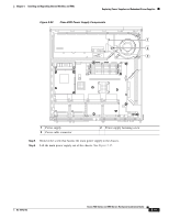
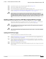
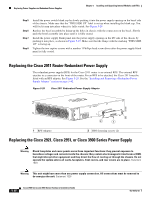
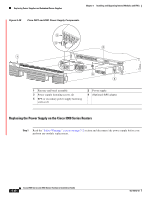
Replacing Power Supplies and Redundant Power Supplies Chapter 5 Installing and Upgrading Internal Modules and FRUs Removing the 2911 DC Power Supply Perform the following steps to remove the 2911 DC power supply: Step 1 Step 2 Step 3 Step 4 Read the "Safety Warnings" section on page 5-2 section and disconnect the power supply before you perform any module removal or installation. Remove the power supply module from the system by loosening the two captive screws using a number 1 Phillips head screwdriver (See Figure 5-26) and pulling the power supply out slowly from the I/O side (See Figure 5-27) of the chassis. Slide the power supply module out of the chassis. If you are not immediately replacing the power supply, install the blank cover over the empty supply slot. See the "Installing the Cisco 2911 Router Power Supply Blank" section on page 5-34. Installing the Cisco 2911 Router Power Supply Blank For safety reasons, the power supply blank cap and panel must be installed immediately if the power supply is removed from the system and the system stays or will be energized before the power supply is replaced. Note This procedure applies to customers who will maintain or supply power to the system with the RPS module. Step 1 Step 2 Step 3 Read the "Safety Warnings" section on page 5-2 section and disconnect the power supply before you perform any module replacement. If the power supply is present, make sure it is turned off and the power cord is detached. Remove it from the system by loosening the two captive screws using a number 1 Phillips head screwdriver and pulling the power supply out slowly from the I/O side of the chassis. See Figure 5-27. 5-34 Cisco 2900 Series and 3900 Series Hardware Installation Guide OL-18712-03
-
 1
1 -
2
-
3
-
4
-
5
-
6
-
7
-
8
-
9
-
10
-
11
-
12
-
13
-
14
-
15
-
16
-
17
-
18
-
19
-
20
-
21
-
22
-
23
-
24
-
25
-
26
-
27
-
28
-
29
-
30
-
31
-
32
-
33
-
34
-
35
-
36
-
37
-
38
-
39
-
40
-
41
-
42
-
43
-
44
-
45
-
46
-
47
-
48
-
49
-
50
-
51
-
52
-
53
-
54
-
55
-
56
-
57
-
58
-
59
-
60
-
61
-
62
-
63
-
64
-
65
-
66
-
67
-
68
-
69
-
70
-
71
-
72
-
73
-
74
-
75
-
76
-
77
-
78
-
79
-
80
-
81
-
82
-
83
-
84
-
85
-
86
-
87
-
88
-
89
-
90
-
91
-
92
-
93
-
94
-
95
-
96
-
97
-
98
-
99
-
100
-
101
-
102
-
103
-
104
-
105
-
106
-
107
-
108
-
109
-
110
-
111
-
112
-
113
-
114
-
115
-
116
-
117
-
118
-
119
-
120
-
121
-
122
-
123
-
124
-
125
-
126
-
127
-
128
-
129
-
130
-
131
-
132
-
133
-
134
-
135
-
136
-
137
-
138
-
139
-
140
-
141
-
142
-
143
-
144
-
145
-
146
-
147
-
148
-
149
-
150
-
151
-
152
-
153
-
154
-
155
-
156
-
157
-
158
-
159
-
160
-
161
-
162
-
163
-
164
-
165
-
166
-
167
-
168
-
169
-
170
-
171
-
172
-
173
-
174
-
175
-
176
-
177
-
178
-
179
-
180
-
 181
181 -
 182
182 -
 183
183 -
 184
184 -
 185
185 -
 186
186 -
 187
187 -
 188
188 -
 189
189 -
 190
190 -
 191
191 -
192
-
193
-
194
-
195
-
196
-
197
-
198
-
199
-
200
-
201
-
202
-
203
-
204
-
205
-
206
-
207
-
208
-
209
-
210
-
211
-
212
-
213
-
214
-
215
-
216
-
217
-
218
-
219
-
220
 |
 |
