Cisco WS-CBS3020-HPQ Installation Guide
Cisco WS-CBS3020-HPQ Manual
 |
View all Cisco WS-CBS3020-HPQ manuals
Add to My Manuals
Save this manual to your list of manuals |
Cisco WS-CBS3020-HPQ manual content summary:
- Cisco WS-CBS3020-HPQ | Installation Guide - Page 1
Cisco IE 3000 Switch Hardware Installation Guide June 2008 Americas Headquarters Cisco Systems, Inc. 170 West Tasman Drive San Jose, CA 95134-1706 USA http://www.cisco.com Tel: 408 526-4000 800 553-NETS (6387) Fax: 408 527-0883 Text Part Number: OL-13017-01 - Cisco WS-CBS3020-HPQ | Installation Guide - Page 2
is a service mark; and Access Registrar, Aironet, AsyncOS, Bringing the Meeting To You, Catalyst, CCDA, CCDP, CCIE, CCIP, CCNA, CCNP, CCSP, CCVP, Cisco, the Cisco Certified Internetwork Expert logo, Cisco IOS, Cisco Press, Cisco Systems, Cisco Systems Capital, the Cisco Systems logo, Cisco Unity - Cisco WS-CBS3020-HPQ | Installation Guide - Page 3
1-10 Dual-Purpose Port LEDs 1-11 Compact Flash Memory Card 1-11 Rear-Panel Description 1-12 Power Converter (Optional) 1-13 Management Options 1-14 Network Configurations 1-15 Switch Installation 2-1 Preparing for Installation 2-1 Warnings 2-2 Cisco IE 3000 Switch Hardware Installation Guide iii - Cisco WS-CBS3020-HPQ | Installation Guide - Page 4
Switch to the Power Converter 2-44 Attaching the Power Converter to the Switch 2-45 Installing the Power Converter on a DIN Rail, Wall, or Rack Adapter 2-46 Connecting the DC Power Clip 2-46 Connecting the Power Converter to an AC Power Source 2-47 Cisco IE 3000 Switch Hardware Installation Guide - Cisco WS-CBS3020-HPQ | Installation Guide - Page 5
the AC Power Cord 2-47 Connecting the AC Power Cord to the Power Converter 2-48 Connecting the Power Converter to a DC Power Source 2-51 Applying Power to the Power Converter 2-53 Where to Go Next 2-53 Troubleshooting 3-1 Diagnosing Problems 3-1 Verify Switch POST Results 3-1 Verify Switch LEDs - Cisco WS-CBS3020-HPQ | Installation Guide - Page 6
Connecting the Power Converter to an AC Power Source B-53 Preparing the AC Power Cord B-53 Connecting the AC Power Cord to the Power Converter B-54 Connecting the Power Converter to a DC Power Source B-57 Applying Power to the Power Converter B-59 Cisco IE 3000 Switch Hardware Installation Guide vi - Cisco WS-CBS3020-HPQ | Installation Guide - Page 7
Adapter Pinouts C-8 Configuring the Switch with the CLI-Based Setup Program D-1 Accessing the CLI from the Console Port D-1 Entering the Initial Configuration Information D-2 IP Settings D-2 Completing the Setup Program D-2 Contents OL-13017-01 Cisco IE 3000 Switch Hardware Installation Guide vii - Cisco WS-CBS3020-HPQ | Installation Guide - Page 8
Contents Cisco IE 3000 Switch Hardware Installation Guide viii OL-13017-01 - Cisco WS-CBS3020-HPQ | Installation Guide - Page 9
the switch getting started guide, the switch software configuration guide, the switch command reference, and the switch system message guide on the Cisco.comTechnical Support and Documentation home page. For information about the standard Cisco IOS Release 12.1 or 12.2 commands, see the Cisco IOS - Cisco WS-CBS3020-HPQ | Installation Guide - Page 10
• Regulatory Compliance and Safety Information for the Cisco IE 3000 Switch • Release Notes for the Cisco IE 3000 Switch • Cisco IE 3000 Switch Software Configuration Guide • Cisco IE 3000 Switch Command Reference • Cisco IE 3000 Switch System Message Guide • Device manager online help (available on - Cisco WS-CBS3020-HPQ | Installation Guide - Page 11
Flash Memory Card, page 1-11 • Rear-Panel Description, page 1-12 • Power Converter (Optional), page 1-13 • Management Options, page 1-14 • Network Configurations, page 1-15 Overview The Cisco IE 3000 switch provides a rugged and secure switching infrastructure for harsh environments. It is suitable - Cisco WS-CBS3020-HPQ | Installation Guide - Page 12
of ports. For instructions on how to connect the expansion modules to the switch, see the "Adding Modules to the Switch" section on page 2-5. . Table 1-1 Cisco IE 3000 Switch Models Switch Model Cisco IE-3000-4TC Cisco IE-3000-8TC Cisco IEM-3000-8TM Cisco IEM-3000-8FM Description 4 10/100BASE - Cisco WS-CBS3020-HPQ | Installation Guide - Page 13
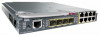
1 Overview Figure 1-1 Cisco IE-3000-8TC Switch 1 2 Front-Panel Description 201699 3 45 1 Power and relay connectors 4 10/100 ports 2 Console port 5 Protective ground connection 3 Dual-purpose ports Figure 1-2 Cisco IE-3000-4TC Switch 1 2 201700 3 45 1 Power and relay connectors - Cisco WS-CBS3020-HPQ | Installation Guide - Page 14
Front-Panel Description Figure 1-3 Cisco IEM-3000-8TM Module Chapter 1 Overview 201702 1 1 10/100 ports Figure 1-4 Cisco IEM-3000-8FM Module 201701 1 1 100BASE-FX ports Cisco IE 3000 Switch Hardware Installation Guide 1-4 OL-13017-01 - Cisco WS-CBS3020-HPQ | Installation Guide - Page 15
primary DC power (supply A) and the major alarm signal, and a second connector (supply B) provides secondary power and the minor alarm signal. The two connectors are physically identical and are in the upper left side of the front panel. See Figure 1-2. OL-13017-01 Cisco IE 3000 Switch Hardware - Cisco WS-CBS3020-HPQ | Installation Guide - Page 16
switch software configuration guide for instructions on configuring the alarm relays. For more information about the power and relay connector, see Appendix C, "Cable and Connectors." You can get replacement power and relay connectors (PWR-IE3000-CNCT=) by calling Cisco Technical Support. Console - Cisco WS-CBS3020-HPQ | Installation Guide - Page 17
Description 201703 5 67 8 1 Express setup button 2 System LED 3 Alarm LED 4 Setup LED 5 Dual-purpose uplink port LED 6 Pwr B LED 7 Pwr A LED 8 Port LED Figure 1-7 LEDs on the Cisco IEM-3000-8TM Module 201706 1 1 10/100 port LED OL-13017-01 Cisco IE 3000 Switch Hardware Installation Guide - Cisco WS-CBS3020-HPQ | Installation Guide - Page 18
setup is incomplete. Switch failed to start initial setup or recovery because there is no available switch port to which to connect the management station. Disconnect a device from a switch port, and then press the Express Setup button. Cisco IE 3000 Switch Hardware Installation Guide 1-8 OL-13017 - Cisco WS-CBS3020-HPQ | Installation Guide - Page 19
Off Green Red System Status Power is not present on the circuit, or the system is not powered up. Power is present on the associated circuit. Power is not present on the associated circuit, and the power supply alarm is configured. OL-13017-01 Cisco IE 3000 Switch Hardware Installation Guide 1-9 - Cisco WS-CBS3020-HPQ | Installation Guide - Page 20
Front-Panel Description Chapter 1 Overview Note The Pwr A and Pwr B LEDs show that power is not present on the switch if the power input drops below the low valid level. The power status LEDs only show that power is present if the voltage at the switch input exceeds the valid level. The difference - Cisco WS-CBS3020-HPQ | Installation Guide - Page 21
meanings as described in Table 1-6. Figure 1-9 Dual-Purpose Port LEDs 1 234 1 203660 1 RJ-45 connector 3 SFP module port in-use LED 2 RJ-45 port in-use LED 4 SFP module slot Compact Flash Memory Card The switch supports a compact flash memory card that makes it possible to replace a failed - Cisco WS-CBS3020-HPQ | Installation Guide - Page 22
Cisco Technical Support. Rear-Panel Description The rear panel of the switch, modules, and power converter switch over a DIN rail and slide inward to secure the switch to a DIN rail. The feet stabilize the switch when it is mounted on the wall. 1-12 Cisco IE 3000 Switch Hardware Installation Guide - Cisco WS-CBS3020-HPQ | Installation Guide - Page 23
1-11 21 Cisco IE 3000 Switch Rear Panel Power Converter (Optional) 201697 1 DIN rail latch 2 Foot in recessed position Power Converter (Optional) The switch can be used with an optional AC/DC power converter. The power converter (PWR-IE3000-AC) can supply 24-VDC power to one switch and up to - Cisco WS-CBS3020-HPQ | Installation Guide - Page 24
1-12 displays the power converter. Figure 1-12 Cisco IE 3000 Switch AC/DC Power Converter 1 2 3 Chapter 1 Overview 202314 1 DC output connector 2 Status LED 3 AC/DC input power connector Management Options The switch supports these management options: • Cisco Network Assistant Cisco Network - Cisco WS-CBS3020-HPQ | Installation Guide - Page 25
platforms such as HP OpenView or SunNet Manager. The switch supports a comprehensive set of Management Information Base (MIB) extensions and four Remote Monitoring (RMON) groups. See the switch software configuration guide on Cisco.com and the documentation that came with your SNMP application - Cisco WS-CBS3020-HPQ | Installation Guide - Page 26
Network Configurations Chapter 1 Overview 1-16 Cisco IE 3000 Switch Hardware Installation Guide OL-13017-01 - Cisco WS-CBS3020-HPQ | Installation Guide - Page 27
the Power Converter, page 2-44 • Where to Go Next, page 2-53 Preparing for Installation This section provides information about these topics: • Warnings, page 2-2 • Installation Guidelines, page 2-3 • Verifying Package Contents, page 2-5 OL-13017-01 Cisco IE 3000 Switch Hardware Installation Guide - Cisco WS-CBS3020-HPQ | Installation Guide - Page 28
power supply connection. All connections must be removed to de-energize the unit. Statement 1028 Warning Only trained and qualified personnel should be allowed to install, replace, or service . 10/100/1000 Ethernet Statement 1044 Cisco IE 3000 Switch Hardware Installation Guide 2-2 OL-13017-01 - Cisco WS-CBS3020-HPQ | Installation Guide - Page 29
to eliminate the risk of ESD damage to the switch. Do not touch connectors or pins on component boards. Do not touch circuit components inside the switch. When not in use, store the equipment in appropriate static-safe packaging. OL-13017-01 Cisco IE 3000 Switch Hardware Installation Guide 2-3 - Cisco WS-CBS3020-HPQ | Installation Guide - Page 30
such as radios, power lines, and fluorescent lighting fixtures. • Connect the unit only to a Class 2 DC power source. Caution This equipment is only suitable for use in Class I, Division 2, Groups A, B, C, D, or nonhazardous locations. Cisco IE 3000 Switch Hardware Installation Guide 2-4 OL-13017 - Cisco WS-CBS3020-HPQ | Installation Guide - Page 31
is missing or damaged, contact your Cisco representative or reseller for support. Return all packing materials to the shipping container and save them. The switch is shipped with these items: • Documentation CD that includes: - Cisco IE 3000 Switch Getting Started Guide (in English, German, French - Cisco WS-CBS3020-HPQ | Installation Guide - Page 32
of the Cisco IE-3000-4TC switch and expansion modules. Even though the example configurations in Figure 2-1 show a Cisco IE-3000-4TC switch, the same combinations of expansion modules can be used with a Cisco IE-3000-8TC switch. Cisco IE 3000 Switch Hardware Installation Guide 2-6 OL-13017 - Cisco WS-CBS3020-HPQ | Installation Guide - Page 33
Chapter 2 Switch Installation Figure 2-1 Sample Combinations of Expansion Modules Adding Modules to the Switch 1 2 3 OL-13017-01 201827 4 Cisco IE 3000 Switch Hardware Installation Guide 2-7 - Cisco WS-CBS3020-HPQ | Installation Guide - Page 34
to the Switch Chapter 2 Switch Installation 1 Cisco IE-3000-4TC switch with Cisco IEM-3000-8TM and Cisco IEM-3000-8FM expansion modules (12 FE and 8 FX ports) 2 Cisco IE-3000-4TC switch with one Cisco IEM-3000-8FM expansion module (4 FE and 8 FX ports) 3 Cisco IE-3000-4TC switch with one Cisco IEM - Cisco WS-CBS3020-HPQ | Installation Guide - Page 35
, and slide the switch and the module together to make the connection. See Figure 2-5. Figure 2-5 Connecting the Switch and the Module 201825 Step 5 Push the upper module latches down and the lower latches up. See Figure 2-6. OL-13017-01 Cisco IE 3000 Switch Hardware Installation Guide 2-9 - Cisco WS-CBS3020-HPQ | Installation Guide - Page 36
the module. Installing or Removing the Compact Flash Memory Card The switches store Cisco IOS software images and switch configurations on a removable flash memory card. You can replace the switch without reconfiguring it. The switch ships with the compact flash memory card installed. Verify that - Cisco WS-CBS3020-HPQ | Installation Guide - Page 37
the steps required to connect a PC or terminal to the switch console port, to power on the switch, and to observe POST results: • Connecting a PC or a Terminal to the Console Port, page 2-12 • Verifying Switch Operation, page 2-11 OL-13017-01 Cisco IE 3000 Switch Hardware Installation Guide 2-11 - Cisco WS-CBS3020-HPQ | Installation Guide - Page 38
you can change the port baud rate. See the switch software configuration guide for instructions. Insert the adapter cable in the console port. See Figure 2-8. (See the "Cable and Adapter Specifications" section on page C-4 for pinout descriptions.) Figure 2-8 Connecting to the Console Port 201868 - Cisco WS-CBS3020-HPQ | Installation Guide - Page 39
ground and DC power to the switch: • Grounding the Switch, page 2-13 • Wiring the DC Power Source, page 2-16 • Attach the Power and Relay Connector to the Switch, page 2-21 Note The Cisco IE 3000 switch can be used with an optional AC/DC power converter (PWR-IE3000-AC). For instructions on how - Cisco WS-CBS3020-HPQ | Installation Guide - Page 40
Stripping the Ground Wire 1 104908 2 3 1 0.5 in. (12.7 mm) ± 0.02 in. (0.5 mm) 3 Wire lead 2 Insulation Step 3 Insert the ground wire into the ring terminal lug, and using a crimping tool, crimp the ring terminal to the wire. 2-14 Cisco IE 3000 Switch Hardware Installation Guide OL-13017-01 - Cisco WS-CBS3020-HPQ | Installation Guide - Page 41
panel. Use a ratcheting torque screwdriver to tighten the ground screw and ring terminal lug to the switch front panel to 8.5 in-lb. The torque should not exceed 8.5 in-lb. See Figure 2- grounded DIN rail, or a grounded bare rack. OL-13017-01 Cisco IE 3000 Switch Hardware Installation Guide 2-15 - Cisco WS-CBS3020-HPQ | Installation Guide - Page 42
or 1569 twisted-pair copper appliance wiring material (AWM) wire (such as Belden part number 9318). To wire the switch to the optional AC/DC converter, go to the "Connecting the Switch to the Power Converter" section on page 2-44. 2-16 Cisco IE 3000 Switch Hardware Installation Guide OL-13017-01 - Cisco WS-CBS3020-HPQ | Installation Guide - Page 43
. Warning An exposed wire lead from a DC-input power source can conduct harmful levels of electricity. Be sure that no exposed portion of the DC-input power source wire extends from the power and relay connector. Statement 122 OL-13017-01 Cisco IE 3000 Switch Hardware Installation Guide 2-17 - Cisco WS-CBS3020-HPQ | Installation Guide - Page 44
to torque the power and relay connector captive screws (above the installed wire leads) to 2 in-lb. See Figure 2-15. Caution Do not over-torque the power and relay connector captive screws. The torque should not exceed 2 in-lb. 2-18 Cisco IE 3000 Switch Hardware Installation Guide OL-13017-01 - Cisco WS-CBS3020-HPQ | Installation Guide - Page 45
second power source, repeat Step 4 through Step 7 using a second power and relay connector. Figure 2-16 shows the completed DC-input wiring on a power and relay connector for a primary power source and an optional secondary power source. OL-13017-01 Cisco IE 3000 Switch Hardware Installation Guide - Cisco WS-CBS3020-HPQ | Installation Guide - Page 46
plan to connect external alarm devices to the alarm relays and the switch is already installed, go to the "Wiring the External Alarms" section on page 2-33. Otherwise, go to the "Verifying Switch Operation" section on page 2-11. 2-20 Cisco IE 3000 Switch Hardware Installation Guide OL-13017-01 - Cisco WS-CBS3020-HPQ | Installation Guide - Page 47
power connector (Pwr A). When you are installing the switch, secure the wires coming from the power and relay connector so that they cannot be disturbed by casual contact. For example, use tie wraps to secure the wires to the rack. OL-13017-01 Cisco IE 3000 Switch Hardware Installation Guide - Cisco WS-CBS3020-HPQ | Installation Guide - Page 48
Power, page 2-22 Power On the Switch To apply power to a switch that is directly connected to a DC power source, locate the circuit breaker on the panel board that services the DC circuit, and switch the circuit breaker to the ON position. Note For instructions on how to apply power to a switch - Cisco WS-CBS3020-HPQ | Installation Guide - Page 49
install the switch: • Installing the Switch on a DIN Rail • Installing the Switch on the Wall • Installing the Switch in a Rack Warning This equipment is supplied as "open type" equipment. It must be mounted within an enclosure that is suitably designed for those specific environmental conditions - Cisco WS-CBS3020-HPQ | Installation Guide - Page 50
in the space next to the tab on each of the latches and turn the screw driver clockwise. See Figure 2-19. Figure 2-19 Unlock the Switch Latch 270302 2-24 Cisco IE 3000 Switch Hardware Installation Guide OL-13017-01 - Cisco WS-CBS3020-HPQ | Installation Guide - Page 51
Installation Step 2 Push the DIN rail latches. See Figure 2-20. Figure 2-20 Pushing the DIN Rail Latches Out Installing the Switch 201828 Step 3 Position the rear panel of the switch directly in front of the DIN rail, making sure that the DIN rail fits in the space between the two latches. OL - Cisco WS-CBS3020-HPQ | Installation Guide - Page 52
Step 4 Push the DIN rail latches in after the switch is over the DIN rail. See Figure 2-21. Figure 2-21 Pushing the DIN Rail Latches In 201829 Note shows the two DIN rails. You can use either the 7.5-mm or the 15-mm DIN rail. 2-26 Cisco IE 3000 Switch Hardware Installation Guide OL-13017-01 - Cisco WS-CBS3020-HPQ | Installation Guide - Page 53
the wall-mounting instructions carefully before beginning installation. Failure to use the correct hardware or to follow the correct procedures could result in a hazardous situation to people and damage to the system. Statement 378 OL-13017-01 Cisco IE 3000 Switch Hardware Installation Guide 2-27 - Cisco WS-CBS3020-HPQ | Installation Guide - Page 54
Installing the Switch Chapter 2 Switch Installation Step 1 If the DIN rail latches are pushed out, push in the DIN rail latches. See Figure 2-23. Figure 2-23 Pushing the DIN Rail Latches In 202370 2-28 Cisco IE 3000 Switch Hardware Installation Guide OL-13017-01 - Cisco WS-CBS3020-HPQ | Installation Guide - Page 55
and alarm wires, as described in the "Connecting Power and Alarm Circuits" section on page 2-32. Installing the Switch in a Rack You can use an optional DIN rail adapter kit (available through Cisco, part number STK-RACKMNT-2955=) to mount the switch in a 19-inch rack. The rack-mounting kit comes - Cisco WS-CBS3020-HPQ | Installation Guide - Page 56
before mounting or servicing the unit in the rack. Statement 1006 Note The 19-inch rack adapter is not intended for application in an industrial environment and therefore it will not meet the environmental performance specifications for the Cisco IE 3000 switch. To install the switch in a rack - Cisco WS-CBS3020-HPQ | Installation Guide - Page 57
Figure 2-26 . Installing the Switch on a Rack Installing the Switch 201831 After the switch is mounted in the rack, connect the power and alarm wires, as described in the "Connecting Power and Alarm Circuits" section on page 2-32. For instructions on how to remove the switch from a rack, see the - Cisco WS-CBS3020-HPQ | Installation Guide - Page 58
connecting the DC power, see the "Connecting the Protective Ground and DC Power" section on page 2-13. For instructions on using a power converter for DC power, see the "Connecting the Switch to the Power Converter" section on page 2-44. 2-32 Cisco IE 3000 Switch Hardware Installation Guide OL - Cisco WS-CBS3020-HPQ | Installation Guide - Page 59
the power and relay connector captive screw (above the installed wire leads) to 2 in-lb. See Figure 2-29 for details. Caution Do not over-torque the power and relay connector captive screws. The torque should not exceed 2 in-lb. OL-13017-01 Cisco IE 3000 Switch Hardware Installation Guide 2-33 - Cisco WS-CBS3020-HPQ | Installation Guide - Page 60
29 Torquing the Power and Relay Connector Captive Screws 202030 V RT A A Step 5 Repeat Step 1 through Step 4 to insert the input and output wires of an additional external alarm device into the second power and relay connector. 2-34 Cisco IE 3000 Switch Hardware Installation Guide OL-13017-01 - Cisco WS-CBS3020-HPQ | Installation Guide - Page 61
8 External device 2, relay wire minor alarm connection See the "Attach the Power and Relay Connector to the Switch" section on page 2-21 for instructions on how to connect the power and relay connector to the front panel. OL-13017-01 Cisco IE 3000 Switch Hardware Installation Guide 2-35 - Cisco WS-CBS3020-HPQ | Installation Guide - Page 62
, to use a twisted four-pair, Category 5 or higher cable. The auto-MDIX feature is enabled by default. For configuration information for this feature, see the switch software configuration guide or the switch command reference. 2-36 Cisco IE 3000 Switch Hardware Installation Guide OL-13017-01 - Cisco WS-CBS3020-HPQ | Installation Guide - Page 63
module slots on the front of the switch. These field-replaceable modules provide the uplink optical interfaces, send (TX) and receive (RX). You can use any combination of rugged SFP modules. See the Cisco IE 3000 release notes for the list of supported modules. Each SFP module must be of the same - Cisco WS-CBS3020-HPQ | Installation Guide - Page 64
send or receive (TX or RX). Align the SFP module sideways in front of the slot opening. Insert the SFP module into the slot until you feel the connector on the module snap into place in the rear of the slot. See Figure 2-33. 2-38 Cisco IE 3000 Switch Hardware Installation Guide OL-13017-01 - Cisco WS-CBS3020-HPQ | Installation Guide - Page 65
remove the dust plugs from the SFP module port or the rubber caps from the fiber-optic cable until you are ready to connect the cable. The plugs and caps protect the SFP module ports and cables from contamination and ambient light. OL-13017-01 Cisco IE 3000 Switch Hardware Installation Guide 2-39 - Cisco WS-CBS3020-HPQ | Installation Guide - Page 66
201867 1 1 Bale clasp Step 5 Step 6 Grasp the SFP module between your thumb and index finger, and carefully remove it from the module slot. Place the removed SFP module in an antistatic bag or other protective environment. 2-40 Cisco IE 3000 Switch Hardware Installation Guide OL-13017-01 - Cisco WS-CBS3020-HPQ | Installation Guide - Page 67
Switch Installation Connecting Destination Ports Connecting to SFP Modules This section describes how to connect to a fiber-optic SFP port. To connect to an RJ-45 Gigabit Ethernet port instead of a fiber-optic port, see the "Connecting to a Dual-Purpose Port" section on page 2-42. For instructions - Cisco WS-CBS3020-HPQ | Installation Guide - Page 68
. See Chapter 3, "Troubleshooting," for solutions to cabling problems. If necessary, reconfigure and restart the switch or the target device. Connecting to a Dual-Purpose Port The dual-purpose port is a single port with two interfaces, one for an RJ-45 cable and another for an SFP module. Only one - Cisco WS-CBS3020-HPQ | Installation Guide - Page 69
SFP module by using the media type interface configuration command. For more information, see the switch command reference. Connecting to 100BASE-FX Ports Follow these steps to connect a fiber-optic cable to an Cisco 2-1. See the "Cable and Adapter Specifications" section on page C-4 for information - Cisco WS-CBS3020-HPQ | Installation Guide - Page 70
. See Chapter 3, "Troubleshooting," for solutions to cabling problems. If necessary, reconfigure and restart the switch or target device. Connecting the Switch to the Power Converter The Cisco IE 3000 switch can be used with an optional AC/DC power converter (PWR-IE3000-AC). These sections describe - Cisco WS-CBS3020-HPQ | Installation Guide - Page 71
of the switch and the power converter) up and the lower module latches (at the bottom of the switch and the power converter) down. See Figure 2-39. Figure 2-39 Pushing the Module Latches Up and Positioning the Hardware 202296 OL-13017-01 Cisco IE 3000 Switch Hardware Installation Guide 2-45 - Cisco WS-CBS3020-HPQ | Installation Guide - Page 72
the DC Power Clip The DC power clip is a prewired cable that connects DC power from the power converter to the switch module. Because the power clip uses the Pwr A connector, you cannot use the alarm connections on that connector. 2-46 Cisco IE 3000 Switch Hardware Installation Guide OL - Cisco WS-CBS3020-HPQ | Installation Guide - Page 73
unterminated AC power cord. See Figure 2-42. Power cord connector types vary by country. Power-cord color codes also vary by country. See Table 2-2. Note Use copper conductors only, rated at a minimum temperature of 167°F (75°C). OL-13017-01 Cisco IE 3000 Switch Hardware Installation Guide 2-47 - Cisco WS-CBS3020-HPQ | Installation Guide - Page 74
to the Power Converter Follow these steps to connect the AC power cord to the power converter. Caution AC power sources must be dedicated AC branch circuits. Each branch circuit must be protected by a dedicated two-pole circuit breaker. 2-48 Cisco IE 3000 Switch Hardware Installation Guide OL - Cisco WS-CBS3020-HPQ | Installation Guide - Page 75
43 AC/DC Power Input Terminal Block 202299 1 1 Ground wire Step 2 Insert the exposed ground wire lead into the power converter ground wire connection. Ensure that only wire with insulation extends from the connector. See Figure 2-44. OL-13017-01 Cisco IE 3000 Switch Hardware Installation Guide - Cisco WS-CBS3020-HPQ | Installation Guide - Page 76
. Note The torque should not exceed 10 in-lb. Step 6 Replace the plastic cover over the terminal block. Step 7 Connect the other end of the AC power cord to the AC outlet. 2-50 Cisco IE 3000 Switch Hardware Installation Guide OL-13017-01 - Cisco WS-CBS3020-HPQ | Installation Guide - Page 77
switch requires. Follow these steps to connect the power converter to a DC power source. Note Use copper conductors only, rated at a minimum temperature of 167°F (75°C). Warning Use twisted-pair supply power power converter to the DC power source. For DC connections from the power converter to the DC - Cisco WS-CBS3020-HPQ | Installation Guide - Page 78
9 Connect the red wire to the positive pole of the DC power source, and connect the black wire to the return pole. Ensure that each pole has a current-limiting-type fuse rated to at least 600 VAC/DC (such as the KLKD Midget fuse). 2-52 Cisco IE 3000 Switch Hardware Installation Guide OL-13017-01 - Cisco WS-CBS3020-HPQ | Installation Guide - Page 79
in the Getting Started with Cisco Network Assistant guide. Through this GUI, you can configure and monitor a switch cluster or an individual switch. • Use the CLI to configure the switch as an individual switch from the console. See the switch command reference on Cisco.com for information about - Cisco WS-CBS3020-HPQ | Installation Guide - Page 80
Where to Go Next Chapter 2 Switch Installation 2-54 Cisco IE 3000 Switch Hardware Installation Guide OL-13017-01 - Cisco WS-CBS3020-HPQ | Installation Guide - Page 81
3-1 • How to Clear the Switch IP Address and Configuration, page 3-5 • How to Recover Passwords, page 3-5 • Finding the Switch Serial Number, page 3-6 Diagnosing Problems The LEDs on the front panel provide troubleshooting information about the switch. They show power-on self-test (POST) failures - Cisco WS-CBS3020-HPQ | Installation Guide - Page 82
, look at the port LEDs for information about the switch. See the "LEDs" section on page 1-6 for a description of the LED colors and their meanings. Verify Switch Connections Review this section when troubleshooting switch connection problems. Bad or Damaged Cable Always make sure that the cable - Cisco WS-CBS3020-HPQ | Installation Guide - Page 83
Troubleshooting Diagnosing Problems module is supported on this platform. (The switch release notes on Cisco.com list the SFP modules that the switch supports.) • Use port or interface is not disabled or powered down for some reason. If a port or interface is manually shut down on one side of the - Cisco WS-CBS3020-HPQ | Installation Guide - Page 84
about enabling UDLD on the switch, see the "Understanding UDLD" section in the "Configuring UDLD" chapter of the software configuration guide for this release. Verify Switch Performance Review this section when troubleshooting switch performance problems. Speed, Duplex, and Autonegotiation If - Cisco WS-CBS3020-HPQ | Installation Guide - Page 85
to Clear the Switch IP Address and Configuration" section on page 3-5. The switch software configuration guide provides details about enabling and disabling the password recovery feature and the procedure for recovering passwords. OL-13017-01 Cisco IE 3000 Switch Hardware Installation Guide 3-5 - Cisco WS-CBS3020-HPQ | Installation Guide - Page 86
Finding the Switch Serial Number Chapter 3 Troubleshooting Finding the Switch Serial Number If you contact Cisco Technical Assistance, you need to know the serial number of your switch. See Figure 3-1 and Figure 3-2 to find the serial number on your switch or module. You can also use the show - Cisco WS-CBS3020-HPQ | Installation Guide - Page 87
specifications for the Cisco IE 3000 switch power converter. The operating temperature for the Cisco IE 3000 switches, modules, and the power convertor varies among environments, based on factors such as the system configuration (60°C). However, the Cisco IE 3000 switch can function in the substation - Cisco WS-CBS3020-HPQ | Installation Guide - Page 88
Power consumption Physical Dimensions Weight Dimensions (W x D x H) -40 to 185°F (-40 to 85°C) 5 to 95% (noncondensing) 20 g at 11 ms Up to 13,000 ft (3962 m) Up to 40,000 ft (12,192 m) Cisco IE-3000-8TC and Cisco IE-3000-4TC: • Range: 18 to 60 VDC • Nominal: 24 or 48 VDC The DC-input power supply - Cisco WS-CBS3020-HPQ | Installation Guide - Page 89
Specifications for the Power Converter Environmental Ranges Operating temperature Storage temperature Operating altitude Storage altitude Thermal spacing Power Requirements AC input voltages Maximum AC power input current DC input voltages Maximum DC input current Physical Dimensions Weight 12.12. - Cisco WS-CBS3020-HPQ | Installation Guide - Page 90
Appendix A Technical Specifications Cisco IE 3000 Switch Hardware Installation Guide A-4 OL-13017-01 - Cisco WS-CBS3020-HPQ | Installation Guide - Page 91
the Power Converter, page B-49 • Where to Go Next, page B-59 Preparing for Installation This section provides information about these topics: • Warnings, page B-2 • Installation Guidelines, page B-5 • Verifying Package Contents, page B-7 OL-13017-01 Cisco IE 3000 Switch Hardware Installation Guide - Cisco WS-CBS3020-HPQ | Installation Guide - Page 92
power supply connection. All connections must be removed to de-energize the unit. Statement 1028 Warning Only trained and qualified personnel should be allowed to install, replace, or service . 10/100/1000 Ethernet Statement 1044 Cisco IE 3000 Switch Hardware Installation Guide B-2 OL-13017-01 - Cisco WS-CBS3020-HPQ | Installation Guide - Page 93
, perform POST on the switch in a nonhazardous location before installation. Statement 1065 Warning Use twisted-pair supply wires suitable for 86°F (30°C) above surrounding ambient temperature outside the enclosure. Statement 1067 OL-13017-01 Cisco IE 3000 Switch Hardware Installation Guide B-3 - Cisco WS-CBS3020-HPQ | Installation Guide - Page 94
power is removed or that the area is nonhazardous before proceeding. Statement 1081 Warning Explosion Hazard-The area must be known to be nonhazardous before installing, servicing 2, Groups A, B, C, D, or nonhazardous locations. Cisco IE 3000 Switch Hardware Installation Guide B-4 OL-13017-01 - Cisco WS-CBS3020-HPQ | Installation Guide - Page 95
Locations and nonhazardous locations only. Each product is supplied with markings on the rating nameplate indicating the the requirements of ETS 300 253 or CCITT K27. • AC-power distribution shall be one of the following types, where applicable: Cisco IE 3000 Switch Hardware Installation Guide B-5 - Cisco WS-CBS3020-HPQ | Installation Guide - Page 96
feet (100 meters). • For 100BASE-FX fiber-optic ports, the cable length from a switch to an attached device cannot exceed 6562 ft (2 km). • Operating environment is within the ranges listed in Appendix A, "Technical Specifications." Cisco IE 3000 Switch Hardware Installation Guide B-6 OL-13017-01 - Cisco WS-CBS3020-HPQ | Installation Guide - Page 97
is missing or damaged, contact your Cisco representative or reseller for support. Return all packing materials to the shipping container and save them. The switch is shipped with these items: • Documentation CD that includes: - Cisco IE 3000 Switch Getting Started Guide (in English, German, French - Cisco WS-CBS3020-HPQ | Installation Guide - Page 98
an dual-LC connector. Adding Modules to the Switch The Cisco IE-3000-4TC or the Cisco IE-3000-8TC switch can operate as standalone devices with four or , you can connect the Cisco IEM-3000-8TM and the Cisco IEM-3000-8FM expansion modules. Depending on the mix of switches and expansion modules, you - Cisco WS-CBS3020-HPQ | Installation Guide - Page 99
of the Cisco IE-3000-4TC switch and expansion modules. Even though the example configurations in Figure B-1 show a Cisco IE-3000-4TC switch, the same combinations of expansion modules can be used with a Cisco IE-3000-8TC switch. OL-13017-01 Cisco IE 3000 Switch Hardware Installation Guide B-9 - Cisco WS-CBS3020-HPQ | Installation Guide - Page 100
Adding Modules to the Switch Appendix B Installation In a Hazardous Environment Figure B-1 Sample Combinations of Expansion Modules 1 2 3 B-10 Cisco IE 3000 Switch Hardware Installation Guide 201827 4 OL-13017-01 - Cisco WS-CBS3020-HPQ | Installation Guide - Page 101
Adding Modules to the Switch 1 Cisco IE-3000-4TC switch with Cisco IEM-3000-8TM and Cisco IEM-3000-8FM expansion modules (12 FE and 8 FX ports) 2 Cisco IE-3000-4TC switch with one Cisco IEM-3000-8FM expansion module (4 FE and 8 FX ports) 3 Cisco IE-3000-4TC switch with one Cisco IEM-3000-8TM - Cisco WS-CBS3020-HPQ | Installation Guide - Page 102
, and slide the switch and the module together to make the connection. See Figure B-5. Figure B-5 Connecting the Switch and the Module 201825 Step 5 Push the upper module latches down and the lower latches up. See Figure B-6. B-12 Cisco IE 3000 Switch Hardware Installation Guide OL-13017-01 - Cisco WS-CBS3020-HPQ | Installation Guide - Page 103
the module. Installing or Removing the Compact Flash Memory Card The switches store Cisco IOS software images and switch configurations on a removable flash memory card. You can replace the switch without reconfiguring it. The switch ships with the compact flash memory card installed. Verify that - Cisco WS-CBS3020-HPQ | Installation Guide - Page 104
the steps required to connect a PC or terminal to the switch console port, to power on the switch, and to observe POST results: • Connecting a PC or a Terminal to the Console Port, page B-15 • Verifying Switch Operation, page B-14 B-14 Cisco IE 3000 Switch Hardware Installation Guide OL-13017-01 - Cisco WS-CBS3020-HPQ | Installation Guide - Page 105
port baud rate. See the switch software configuration guide for instructions. Insert the adapter cable in the console port. See Figure B-8. (See the "Cable and Adapter Specifications" section on page C-4 for pinout descriptions.) OL-13017-01 Cisco IE 3000 Switch Hardware Installation Guide B-15 - Cisco WS-CBS3020-HPQ | Installation Guide - Page 106
ground and DC power to the switch: • Grounding the Switch, page B-17 • Wiring the DC Power Source, page B-19 • Attach the Power and Relay Connector to the Switch, page B-24 Note The Cisco IE 3000 switch can be used with an optional AC/DC power converter (PWR-IE3000-AC). For instructions on how - Cisco WS-CBS3020-HPQ | Installation Guide - Page 107
equivalent) • For DC power connections, use UL- 12 AWG wire, such as Thomas & Bett part number 10RCR or equivalent. Step 2 Use a wire-stripping tool to strip the 10- gauge wire to 0.5 inch (12.7 mm) ± 0.02 inch (0.5 mm). See Figure B-9. OL-13017-01 Cisco IE 3000 Switch Hardware Installation Guide - Cisco WS-CBS3020-HPQ | Installation Guide - Page 108
Verifying Switch Operation Figure B-9 Stripping the Ground Wire 1 Appendix B Installation In a Hazardous Environment 104908 2 3 1 0.5 in. (12.7 mm) ± 0.02 in. (0.5 mm) to the switch front panel to 8.5 in-lb. See Figure B-11. B-18 Cisco IE 3000 Switch Hardware Installation Guide OL-13017-01 - Cisco WS-CBS3020-HPQ | Installation Guide - Page 109
a grounded bare rack. Wiring the DC Power Source Read these warnings before wiring the DC power source: Caution This product is intended to be supplied by a Listed Class 2 power source marked with "Class 2" and . Statement 1074 OL-13017-01 Cisco IE 3000 Switch Hardware Installation Guide B-19 - Cisco WS-CBS3020-HPQ | Installation Guide - Page 110
should be allowed to install, replace, or service this equipment. Statement 1030 Caution You must connect the switch only to a DC-input power source that has an input supply voltage from 18 to 60 VDC. If the supply voltage is not in this range, the switch might not operate properly or might be - Cisco WS-CBS3020-HPQ | Installation Guide - Page 111
to torque the power and relay connector captive screws (above the installed wire leads) to 2 in-lb. See Figure B-15. Caution Do not over-torque the power and relay connector captive screws. The torque should not exceed 2 in-lb. OL-13017-01 Cisco IE 3000 Switch Hardware Installation Guide B-21 - Cisco WS-CBS3020-HPQ | Installation Guide - Page 112
on the DC power source. When you are testing the switch, one power connection is sufficient. If you are installing the switch and are using a second power source, repeat Step 4 through Step 7 using a second power and relay connector. B-22 Cisco IE 3000 Switch Hardware Installation Guide OL-13017 - Cisco WS-CBS3020-HPQ | Installation Guide - Page 113
In a Hazardous Environment Verifying Switch Operation Figure B-16 shows the completed DC-input wiring on a power and relay connector for a primary power source and an optional secondary power source. Figure B-16 Completed DC Power Connections on the Power and Relay Connector 1 2 3 4 V RT - Cisco WS-CBS3020-HPQ | Installation Guide - Page 114
primary power connector (Pwr A). When you are installing the switch, secure the wires coming from the power and relay connector so that they cannot be disturbed by casual contact. For example, use tie wraps to secure the wires to the rack. B-24 Cisco IE 3000 Switch Hardware Installation Guide OL - Cisco WS-CBS3020-HPQ | Installation Guide - Page 115
Power, page B-25 Power On the Switch To apply power to a switch that is directly connected to a DC power source, locate the circuit breaker on the panel board that services the DC circuit, and switch the circuit breaker to the ON position. Note For instructions on how to apply power to a switch - Cisco WS-CBS3020-HPQ | Installation Guide - Page 116
switch: • Installing the Switch on a DIN Rail • Installing the Switch on a Wall • Installing the Switch in a Rack Warning This equipment is supplied as "open type" equipment. It must be mounted within an enclosure that is suitably designed for those specific all power, input the switch from - Cisco WS-CBS3020-HPQ | Installation Guide - Page 117
"Adding Modules to the Switch" section on page B-8. The illustrations in this procedure show how to install the switch as a standalone device. The same steps can be used to install a switch with expansion modules on the DIN rail. OL-13017-01 Cisco IE 3000 Switch Hardware Installation Guide B-27 - Cisco WS-CBS3020-HPQ | Installation Guide - Page 118
in the space next to the tab on each of the latches and turn the screw driver clockwise. See Figure B-19. Figure B-19 Unlock the Switch Latch 270302 B-28 Cisco IE 3000 Switch Hardware Installation Guide OL-13017-01 - Cisco WS-CBS3020-HPQ | Installation Guide - Page 119
Environment Step 2 Push the DIN rail latches out. See Figure B-20. Figure B-20 Pushing the DIN Rail Latches Out Installing the Switch 201828 Step 3 Position the rear panel of the switch directly in front of the DIN rail, making sure that the DIN rail fits in the space between the two latches - Cisco WS-CBS3020-HPQ | Installation Guide - Page 120
B Installation In a Hazardous Environment Step 4 Push the DIN rail latches in after the switch is over the DIN rail. See Figure B-21. Figure B-21 Pushing the DIN Rail rails. You can use either the 7.5-mm or the 15-mm DIN rail. B-30 Cisco IE 3000 Switch Hardware Installation Guide OL-13017-01 - Cisco WS-CBS3020-HPQ | Installation Guide - Page 121
the wall-mounting instructions carefully before beginning installation. Failure to use the correct hardware or to follow the correct procedures could result in a hazardous situation to people and damage to the system. Statement 378 OL-13017-01 Cisco IE 3000 Switch Hardware Installation Guide B-31 - Cisco WS-CBS3020-HPQ | Installation Guide - Page 122
Installing the Switch Appendix B Installation In a Hazardous Environment Step 1 If the DIN rail latches are pushed out, push in the DIN rail latches. See Figure B-23. Figure B-23 Pushing the DIN Rail Latches In 202370 B-32 Cisco IE 3000 Switch Hardware Installation Guide OL-13017-01 - Cisco WS-CBS3020-HPQ | Installation Guide - Page 123
and alarm wires, as described in the "Connecting Power and Alarm Circuits" section on page B-36. Installing the Switch in a Rack You can use an optional DIN rail adapter kit (available through Cisco, part number STK-RACKMNT-2955=) to mount the switch in a 19-inch rack. The rack-mounting kit comes - Cisco WS-CBS3020-HPQ | Installation Guide - Page 124
before mounting or servicing the unit in the rack. Statement 1006 Note The 19-inch rack adapter is not intended for application in an industrial environment and therefore it will not meet the environmental performance specifications for the Cisco IE 3000 switch. To install the switch in a rack - Cisco WS-CBS3020-HPQ | Installation Guide - Page 125
Figure B-26 . Installing the Switch on a Rack Installing the Switch 201831 After the switch is mounted in the rack, connect the power and alarm wires, as described in the "Connecting Power and Alarm Circuits" section on page B-36. For instructions on how to remove the switch from a rack, see the - Cisco WS-CBS3020-HPQ | Installation Guide - Page 126
After the switch is installed, you are ready to connect the DC power and alarm relays. • Information about the Sealed Relay Device, page B-37 • Wiring the Protective Ground and DC Power, page B-37 • Wiring the External Alarms, page B-38 B-36 Cisco IE 3000 Switch Hardware Installation Guide OL - Cisco WS-CBS3020-HPQ | Installation Guide - Page 127
the DC power, see the "Connecting the Protective Ground and DC Power" section on page B-16. For instructions on using a power converter for DC power, see the "Connecting the Switch to the Power Converter" section on page B-49. OL-13017-01 Cisco IE 3000 Switch Hardware Installation Guide B-37 - Cisco WS-CBS3020-HPQ | Installation Guide - Page 128
requires two connections to a relay, the switch supports a maximum of two external alarm devices. This Power and Relay Connector 1 2 V RT A A 202029 1 External device, relay wire A connection 1 2 External device, relay wire A connection 2 B-38 Cisco IE 3000 Switch Hardware Installation Guide - Cisco WS-CBS3020-HPQ | Installation Guide - Page 129
29 Torquing the Power and Relay Connector Captive Screws 202030 V RT A A Step 5 Repeat Step 1 through Step 4 to insert the input and output wires of an additional external alarm device into the second power and relay connector. OL-13017-01 Cisco IE 3000 Switch Hardware Installation Guide B-39 - Cisco WS-CBS3020-HPQ | Installation Guide - Page 130
8 External device 2, relay wire minor alarm connection See the "Attach the Power and Relay Connector to the Switch" section on page B-24 for instructions on how to connect the power and relay connector to the front panel. B-40 Cisco IE 3000 Switch Hardware Installation Guide OL-13017-01 - Cisco WS-CBS3020-HPQ | Installation Guide - Page 131
devices, use a twisted four-pair, Category 5 or higher cable. The auto-MDIX feature is enabled by default. For configuration information for this feature, see the switch software configuration guide or the switch command reference. OL-13017-01 Cisco IE 3000 Switch Hardware Installation Guide B-41 - Cisco WS-CBS3020-HPQ | Installation Guide - Page 132
module slots on the front of the switch. These field-replaceable modules provide the uplink optical interfaces, send (TX) and receive (RX). You can use any combination of rugged SFP modules. See the Cisco IE 3000 release notes for the list of supported modules. Each SFP module must be of the same - Cisco WS-CBS3020-HPQ | Installation Guide - Page 133
send or receive (TX or RX). Align the SFP module sideways in front of the slot opening. Insert the SFP module into the slot until you feel the connector on the module snap into place in the rear of the slot. See Figure B-33. OL-13017-01 Cisco IE 3000 Switch Hardware Installation Guide B-43 - Cisco WS-CBS3020-HPQ | Installation Guide - Page 134
light. Step 6 Insert the LC cable connector into the SFP module. Removing SFP Modules from SFP Module Slots To remove an SFP module from a module receptacle, follow these steps: Step 1 instrument to open the bale-clasp latch. B-44 Cisco IE 3000 Switch Hardware Installation Guide OL-13017-01 - Cisco WS-CBS3020-HPQ | Installation Guide - Page 135
to the SFP module, be sure that you understand the port and cabling stipulations in the "Preparing for Installation" section on page B-1. See Appendix C, "Cable and Connectors," for information about the LC on the SFP module. OL-13017-01 Cisco IE 3000 Switch Hardware Installation Guide B-45 - Cisco WS-CBS3020-HPQ | Installation Guide - Page 136
. See Chapter 3, "Troubleshooting," for solutions to cabling problems. If necessary, reconfigure and restart the switch or the target device. Connecting to a Dual-Purpose Port The dual-purpose port is a single port with two interfaces, one for an RJ-45 cable and another for an SFP module. Only one - Cisco WS-CBS3020-HPQ | Installation Guide - Page 137
. You can change this setting and configure the port to recognize only an RJ-45 connector or only an SFP module by using the media type interface configuration command. For more information, see the switch command reference. OL-13017-01 Cisco IE 3000 Switch Hardware Installation Guide B-47 - Cisco WS-CBS3020-HPQ | Installation Guide - Page 138
green when the switch and the target device have an established link. The LED turns amber while the STP discovers the network topology and searches for loops. This process takes about 30 seconds, and then the port LED turns green. B-48 Cisco IE 3000 Switch Hardware Installation Guide OL-13017-01 - Cisco WS-CBS3020-HPQ | Installation Guide - Page 139
. See Chapter 3, "Troubleshooting," for solutions to cabling problems. If necessary, reconfigure and restart the switch or target device. Connecting the Switch to the Power Converter The Cisco IE 3000 switch can be used with an optional AC/DC power converter (PWR-IE3000-AC). These sections describe - Cisco WS-CBS3020-HPQ | Installation Guide - Page 140
panel of the switch by firmly grasping both sides of it in the middle and pulling it outward. If necessary, use a screwdriver to open the side panel. See Figure B-38. Figure B-38 Opening the Left Side Panel of the Switch 202295 B-50 Cisco IE 3000 Switch Hardware Installation Guide OL-13017-01 - Cisco WS-CBS3020-HPQ | Installation Guide - Page 141
so that the power module fits in the switch recess. Push the upper module latches down and the lower module latches up to secure the power converter to the switch. See Figure B- Alarm Pwr B 7 Setup 1 3 8 2 4 Cisco Catalyst OL-13017-01 Cisco IE 3000 Switch Hardware Installation Guide B-51 - Cisco WS-CBS3020-HPQ | Installation Guide - Page 142
kit. Position the power clip so that the two-pin connector is over the power converter and the four-pin connector is over the switch Pwr A connector, and then slide the power clip into these two connectors. See Figure B-41. B-52 Cisco IE 3000 Switch Hardware Installation Guide OL-13017-01 - Cisco WS-CBS3020-HPQ | Installation Guide - Page 143
, unterminated AC power cord. See Figure B-42. Power cord connector types vary by country. Power-cord color codes also vary by country. See Table 2-2. Note Use copper conductors only, rated at a minimum temperature of 167°F (75°C). OL-13017-01 Cisco IE 3000 Switch Hardware Installation Guide B-53 - Cisco WS-CBS3020-HPQ | Installation Guide - Page 144
to the Power Converter Follow these steps to connect the AC power cord to the power converter. Caution AC power sources must be dedicated AC branch circuits. Each branch circuit must be protected by a dedicated two-pole circuit breaker. B-54 Cisco IE 3000 Switch Hardware Installation Guide OL - Cisco WS-CBS3020-HPQ | Installation Guide - Page 145
AC/DC Power Input Terminal Block 202299 1 1 Ground wire Step 2 Insert the exposed ground wire lead into the power converter ground wire connection. Make sure that only wire with insulation extends from the connector. See Figure B-44. OL-13017-01 Cisco IE 3000 Switch Hardware Installation Guide - Cisco WS-CBS3020-HPQ | Installation Guide - Page 146
. Note The torque should not exceed 10 in-lb. Step 6 Replace the plastic cover over the terminal block. Step 7 Connect the other end of the AC power cord to the AC outlet. B-56 Cisco IE 3000 Switch Hardware Installation Guide OL-13017-01 - Cisco WS-CBS3020-HPQ | Installation Guide - Page 147
switch requires. Follow these steps to connect the power converter to a DC power source. Note Use copper conductors only, rated at a minimum temperature of 167°F (75°C). Warning Use twisted-pair supply power power converter to the DC power source. For DC connections from the power converter to the DC - Cisco WS-CBS3020-HPQ | Installation Guide - Page 148
9 Connect the red wire to the positive pole of the DC power source, and connect the black wire to the return pole. Ensure that each pole has a current-limiting-type fuse rated to at least 600 VAC/DC (such as the KLKD Midget fuse). B-58 Cisco IE 3000 Switch Hardware Installation Guide OL-13017-01 - Cisco WS-CBS3020-HPQ | Installation Guide - Page 149
in the Getting Started with Cisco Network Assistant guide. Through this GUI, you can configure and monitor a switch cluster or an individual switch. • Use the CLI to configure the switch as an individual switch from the console. See the switch command reference on Cisco.com for information about - Cisco WS-CBS3020-HPQ | Installation Guide - Page 150
Where to Go Next Appendix B Installation In a Hazardous Environment B-60 Cisco IE 3000 Switch Hardware Installation Guide OL-13017-01 - Cisco WS-CBS3020-HPQ | Installation Guide - Page 151
C-2 show the pinouts. The auto-MDIX feature described briefly in this guide is enabled by default. For configuration information for this feature, see the switch software configuration guide or the switch command reference. Connecting to 10BASE-T- and 100BASE-TX-Compatible Devices When connecting - Cisco WS-CBS3020-HPQ | Installation Guide - Page 152
Connector Specifications Appendix C Cable and Connectors Note Use a straight-through cable to connect two ports only when C-2 Pin 1 2 3 4 5 6 7 8 10/100/1000 Port Pinouts Label TP0+ TP0TP1+ TP2+ TP2TP1TP3+ TP3- 12345678 60915 Cisco IE 3000 Switch Hardware Installation Guide C-2 OL-13017-01 - Cisco WS-CBS3020-HPQ | Installation Guide - Page 153
from disconnected fibers or connectors. Do not stare into beams or view directly with optical instruments. Figure C-4 Pin 1 2 3 4 5 6 7 8 Copper SFP Module RJ-45 Connector Label 12345678 TP0+ TP0TP1+ TP2+ TP2TP1TP3+ TP3- 60915 OL-13017-01 Cisco IE 3000 Switch Hardware Installation Guide C-3 - Cisco WS-CBS3020-HPQ | Installation Guide - Page 154
-optic and copper uplink ports. See the switch release notes for a list of supported SFP modules. The auto-MDIX feature is enabled by default. For configuration information for this feature, see the switch software configuration guide or the switch command reference. Console Port The console port - Cisco WS-CBS3020-HPQ | Installation Guide - Page 155
and Adapter Specifications Table C-1 Rugged Fiber-Optic SFP Module Port Cabling Specifications SFP Module Wavelength Switch 3 TD+ 6 TD- 1 RD+ 2 RD- Two Twisted-Pair Crossover Cable Schematic Switch 3 TD+ 6 TD- 1 RD+ 2 RD- H5579 OL-13017-01 Cisco IE 3000 Switch Hardware Installation Guide - Cisco WS-CBS3020-HPQ | Installation Guide - Page 156
Cable and Adapter Specifications Appendix C Cable and Connectors Four Twisted-Pair Cable Pinouts for 1000BASE-T Ports Figure C-7 and Figure C-8 show the schematics of four twisted-pair cables for 10/100/1000 ports on the Cisco IE 3000 switches. Figure C-7 Switch 1 TPO+ 2 TPO3 TP1+ 6 TP1- Four - Cisco WS-CBS3020-HPQ | Installation Guide - Page 157
switches. Figure C-10 Switch 1 TPO+ 2 TPO3 TP1+ 6 TP1- Four Twisted-Pair Straight-Through Cable Schematic for 10/100/1000 Ports Router or PC 1 TP1+ 2 TP13 TPO+ 6 TPO- 4 TP2+ 5 TP27 TP3+ 8 TP3- 4 TP3+ 5 TP37 TP2+ 8 TP2- 65272 OL-13017-01 Cisco IE 3000 Switch Hardware Installation Guide C-7 - Cisco WS-CBS3020-HPQ | Installation Guide - Page 158
Cable and Adapter Specifications Appendix C Cable and Connectors Figure C-11 Switch 1 TPO+ 2 TPO3 TP1+ 6 TP1- 4 TP2+ 5 TP27 TP3+ 8 TP3- 65274 Four Twisted-Pair Crossover Cable Schematics for 10/100/1000 and 1000BASE-T SFP Module Ports Switch 1 TP0+ 2 TP03 TP1+ 6 TP1- 4 TP2+ 5 TP27 TP3+ 8 TP3- - Cisco WS-CBS3020-HPQ | Installation Guide - Page 159
Adapter Specifications Table C-3 lists the pinouts for the console port, RJ-45-to-DB-25 female DTE adapter, and the console device. Note The RJ-45-to-DB-25 female DTE adapter is not supplied with the switch. You can order a kit (part number ACS-DSBUASYN=) containing this adapter from Cisco. Table - Cisco WS-CBS3020-HPQ | Installation Guide - Page 160
Cable and Adapter Specifications Appendix C Cable and Connectors C-10 Cisco IE 3000 Switch Hardware Installation Guide OL-13017-01 - Cisco WS-CBS3020-HPQ | Installation Guide - Page 161
D I X Configuring the Switch with the CLI-Based Setup Program This appendix provides a command-line interface (CLI)-based setup procedure for a standalone switch. For information about setting up the switch by using Express Setup, see the Cisco IE 3000 Switch Getting Started Guide. Before connecting - Cisco WS-CBS3020-HPQ | Installation Guide - Page 162
or Cisco Network Assistant to configure and manage the switch. IP Settings You need this information from your network administrator before you complete the setup program: • Switch IP address • Subnet mask (IP netmask) • Default gateway (router) • Enable secret password • Enable password • Telnet - Cisco WS-CBS3020-HPQ | Installation Guide - Page 163
now completed the initial configuration of the switch, and the switch displays its initial configuration script: The following configuration command script was created: hostname Switch enable secret 5 $1$ZQRe$DPulYXyQLm77v/a4Bmu6Y. enable password cisco line vty 0 15 password cisco no snmp-server - Cisco WS-CBS3020-HPQ | Installation Guide - Page 164
by using Telnet. For configuration information, see the switch software configuration guide or the switch command reference. To use the Cisco Network Assistant, see the Getting Started with Cisco Network Assistant guide on Cisco.com. Cisco IE 3000 Switch Hardware Installation Guide D-4 OL-13017-01 - Cisco WS-CBS3020-HPQ | Installation Guide - Page 165
ports cable lengths 2-4, B-6 connecting to 2-36, B-41 described 1-5 1000BASE-T ports C-6 100BASE-FX ports cable lengths 2-4, B-6 cable specifications C-5 connecting to 2-43, B-48 described 1-5 A AC/DC power converter, connecting to 2-44 to 2-53, B-49 to B-59 adapter pinouts, terminal RJ-45-to-DB-25 - Cisco WS-CBS3020-HPQ | Installation Guide - Page 166
console port 2-12, B-15 device manager described 1-14 to configure switch 2-53, B-59 diagnosing problems 3-1 dimensions A-2 to A-3 dual-purpose ports connectors and cables C-4 described 1-5 LEDs 1-11 IN-2 Cisco IE 3000 Switch Hardware Installation Guide duplex, troubleshooting 3-4 E electrical - Cisco WS-CBS3020-HPQ | Installation Guide - Page 167
lightning activity warning 2-2, B-2 link status troubleshooting 3-3 M management options 1-14 to 1-15 module configurations 2-6, B-9 connecting 2-8, B-11 mounting rack 2-29 to 2-31, B-33 to B-35 MT-RJ connector C-3 See also 100BASE-FX ports Cisco IE 3000 Switch Hardware Installation Guide IN-3 - Cisco WS-CBS3020-HPQ | Installation Guide - Page 168
FX ports, 100BASE-LX ports, and console ports POST description 2-22, 2-53, 3-1, B-25, B-59 IN-4 Cisco IE 3000 Switch Hardware Installation Guide LEDs 3-1 results 2-22, 2-53, 3-1, B-25, B-59 running at power on 3-1 power connecting to AC 2-47, B-53 DC 2-16 to 2-22, B-19 to B-25 requirements A-2 to - Cisco WS-CBS3020-HPQ | Installation Guide - Page 169
01 T technical specifications A-1 to A-2 Telnet, and accessing the CLI 1-14 temperature, operating A-3 terminal, connecting to a switch 2-12 to 2-13, B-15 to B-16 terminal-emulation software 2-12, B-15 troubleshooting bad or damaged cable 3-2 connection problems 3-2 diagnosing problems 3-1 Ethernet - Cisco WS-CBS3020-HPQ | Installation Guide - Page 170
Index warnings (continued) lightning activity 2-2, B-2 national laws and regulations 2-2 qualified personnel 2-2, B-2 restricted access areas 2-2, B-2 supply wires 2-51, B-3, B-57 wiring the relays 2-33 to 2-35, B-38 to B-40 IN-6 Cisco IE 3000 Switch Hardware Installation Guide OL-13017-01
-
 1
1 -
 2
2 -
 3
3 -
 4
4 -
 5
5 -
 6
6 -
 7
7 -
8
-
9
-
10
-
11
-
12
-
13
-
14
-
15
-
16
-
17
-
18
-
19
-
20
-
21
-
22
-
23
-
24
-
25
-
26
-
27
-
28
-
29
-
30
-
31
-
32
-
33
-
34
-
35
-
36
-
37
-
38
-
39
-
40
-
41
-
42
-
43
-
44
-
45
-
46
-
47
-
48
-
49
-
50
-
51
-
52
-
53
-
54
-
55
-
56
-
57
-
58
-
59
-
60
-
61
-
62
-
63
-
64
-
65
-
66
-
67
-
68
-
69
-
70
-
71
-
72
-
73
-
74
-
75
-
76
-
77
-
78
-
79
-
80
-
81
-
82
-
83
-
84
-
85
-
86
-
87
-
88
-
89
-
90
-
91
-
92
-
93
-
94
-
95
-
96
-
97
-
98
-
99
-
100
-
101
-
102
-
103
-
104
-
105
-
106
-
107
-
108
-
109
-
110
-
111
-
112
-
113
-
114
-
115
-
116
-
117
-
118
-
119
-
120
-
121
-
122
-
123
-
124
-
125
-
126
-
127
-
128
-
129
-
130
-
131
-
132
-
133
-
134
-
135
-
136
-
137
-
138
-
139
-
140
-
141
-
142
-
143
-
144
-
145
-
146
-
147
-
148
-
149
-
150
-
151
-
152
-
153
-
154
-
155
-
156
-
157
-
158
-
159
-
160
-
161
-
162
-
163
-
164
-
165
-
166
-
167
-
168
-
169
-
170
 |
 |

Americas Headquarters
Cisco Systems, Inc.
170 West Tasman Drive
San Jose, CA 95134-1706
USA
Tel: 408 526-4000
800 553-NETS (6387)
Fax: 408 527-0883
Cisco IE 3000 Switch Hardware
Installation Guide
June 2008
Text Part Number: OL-13017-01