Cisco WS-CBS3020-HPQ Installation Guide - Page 138
B-37, Connecting to a Fiber-Optic SFP Module Port
 |
View all Cisco WS-CBS3020-HPQ manuals
Add to My Manuals
Save this manual to your list of manuals |
Page 138 highlights
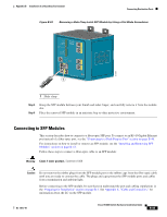
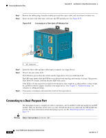
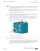
Connecting Destination Ports Appendix B Installation In a Hazardous Environment Connecting to 100BASE-FX Ports Follow these steps to connect a fiber-optic cable to an Cisco IEM-3000-8FM expansion module: Warning Class 1 laser product. Statement 1008 Caution Do not remove the rubber plugs from the SFF module port or the rubber caps from the fiber-optic cable until you are ready to connect the cable. The plugs and caps protect the SFF module ports and cables from contamination and ambient light. Before connecting to the SFF module, be sure that you understand the port and cabling stipulations in the "Preparing for Installation" section on page B-1. See the "Cable and Adapter Specifications" section on page C-4 for information about the LC connector on the SFP module. Step 1 Remove the rubber plugs from the module port and fiber-optic cable, and store them for future use. Step 2 Insert one end of the fiber-optic cable into the SFP module port. See Figure B-35. Figure B-37 Connecting to a Fiber-Optic SFP Module Port 1 202031 1 LC connector Step 3 Step 4 Insert the other cable end into a fiber-optic receptacle on a target device. Observe the port status LED. The LED turns green when the switch and the target device have an established link. The LED turns amber while the STP discovers the network topology and searches for loops. This process takes about 30 seconds, and then the port LED turns green. B-48 Cisco IE 3000 Switch Hardware Installation Guide OL-13017-01
-
 1
1 -
2
-
3
-
4
-
5
-
6
-
7
-
8
-
9
-
10
-
11
-
12
-
13
-
14
-
15
-
16
-
17
-
18
-
19
-
20
-
21
-
22
-
23
-
24
-
25
-
26
-
27
-
28
-
29
-
30
-
31
-
32
-
33
-
34
-
35
-
36
-
37
-
38
-
39
-
40
-
41
-
42
-
43
-
44
-
45
-
46
-
47
-
48
-
49
-
50
-
51
-
52
-
53
-
54
-
55
-
56
-
57
-
58
-
59
-
60
-
61
-
62
-
63
-
64
-
65
-
66
-
67
-
68
-
69
-
70
-
71
-
72
-
73
-
74
-
75
-
76
-
77
-
78
-
79
-
80
-
81
-
82
-
83
-
84
-
85
-
86
-
87
-
88
-
89
-
90
-
91
-
92
-
93
-
94
-
95
-
96
-
97
-
98
-
99
-
100
-
101
-
102
-
103
-
104
-
105
-
106
-
107
-
108
-
109
-
110
-
111
-
112
-
113
-
114
-
115
-
116
-
117
-
118
-
119
-
120
-
121
-
122
-
123
-
124
-
125
-
126
-
127
-
128
-
129
-
130
-
131
-
132
-
 133
133 -
 134
134 -
 135
135 -
 136
136 -
 137
137 -
 138
138 -
 139
139 -
 140
140 -
 141
141 -
 142
142 -
 143
143 -
144
-
145
-
146
-
147
-
148
-
149
-
150
-
151
-
152
-
153
-
154
-
155
-
156
-
157
-
158
-
159
-
160
-
161
-
162
-
163
-
164
-
165
-
166
-
167
-
168
-
169
-
170
 |
 |
