Cisco WS-CBS3020-HPQ Installation Guide - Page 19
System LED, Alarm LED, Power Status LED, Color, System Status
 |
View all Cisco WS-CBS3020-HPQ manuals
Add to My Manuals
Save this manual to your list of manuals |
Page 19 highlights
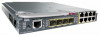
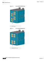
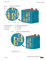
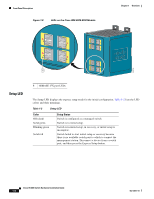
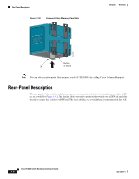
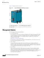
Chapter 1 Overview Front-Panel Description System LED The System LED shows whether the system is receiving power and is functioning properly. Table 1-3 lists the system LED colors and their meanings. Table 1-3 System LED Color Off Green Red System Status System is not powered on. System is operating normally. Switch is not functioning properly. Alarm LED Table 1-4 lists the alarm LED colors and their meanings. Table 1-4 Alarm Status LED Color System Status Off Alarms are not configured, or the switch is off. Green Alarms are configured. Blinking red Switch has detected a major alarm. Red Switch has detected a minor alarm. Power Status LED The switch can operate with one or two DC power sources. Each DC input has an associated LED that shows the status of the corresponding DC input. If power is present on the circuit, the LED is green. If power is not present, the LED color depends on the alarm configuration. If alarms are configured, the LED is red when power is not present; otherwise, the LED is off. If the switch has dual power sources, the switch draws power from the power source with the higher voltage. If the one of the DC sources fails, the alternate DC source powers the switch, and the corresponding power status LED is green. The power status for the failed DC source is either off or red, depending on the alarm configuration. Table 1-5 lists the power status LED colors and meanings. Table 1-5 Power Status LEDs Color Off Green Red System Status Power is not present on the circuit, or the system is not powered up. Power is present on the associated circuit. Power is not present on the associated circuit, and the power supply alarm is configured. OL-13017-01 Cisco IE 3000 Switch Hardware Installation Guide 1-9
-
 1
1 -
2
-
3
-
4
-
5
-
6
-
7
-
8
-
9
-
10
-
11
-
12
-
13
-
 14
14 -
 15
15 -
 16
16 -
 17
17 -
 18
18 -
 19
19 -
 20
20 -
 21
21 -
 22
22 -
 23
23 -
 24
24 -
25
-
26
-
27
-
28
-
29
-
30
-
31
-
32
-
33
-
34
-
35
-
36
-
37
-
38
-
39
-
40
-
41
-
42
-
43
-
44
-
45
-
46
-
47
-
48
-
49
-
50
-
51
-
52
-
53
-
54
-
55
-
56
-
57
-
58
-
59
-
60
-
61
-
62
-
63
-
64
-
65
-
66
-
67
-
68
-
69
-
70
-
71
-
72
-
73
-
74
-
75
-
76
-
77
-
78
-
79
-
80
-
81
-
82
-
83
-
84
-
85
-
86
-
87
-
88
-
89
-
90
-
91
-
92
-
93
-
94
-
95
-
96
-
97
-
98
-
99
-
100
-
101
-
102
-
103
-
104
-
105
-
106
-
107
-
108
-
109
-
110
-
111
-
112
-
113
-
114
-
115
-
116
-
117
-
118
-
119
-
120
-
121
-
122
-
123
-
124
-
125
-
126
-
127
-
128
-
129
-
130
-
131
-
132
-
133
-
134
-
135
-
136
-
137
-
138
-
139
-
140
-
141
-
142
-
143
-
144
-
145
-
146
-
147
-
148
-
149
-
150
-
151
-
152
-
153
-
154
-
155
-
156
-
157
-
158
-
159
-
160
-
161
-
162
-
163
-
164
-
165
-
166
-
167
-
168
-
169
-
170
 |
 |
