Cisco WS-CBS3020-HPQ Installation Guide - Page 108
B-9, Stripping the Ground Wire, Crimping the Ring Terminal, Step 3
 |
View all Cisco WS-CBS3020-HPQ manuals
Add to My Manuals
Save this manual to your list of manuals |
Page 108 highlights
Verifying Switch Operation Figure B-9 Stripping the Ground Wire 1 Appendix B Installation In a Hazardous Environment 104908 2 3 1 0.5 in. (12.7 mm) ± 0.02 in. (0.5 mm) 2 Insulation 3 Wire lead Step 3 Insert the ground wire into the ring terminal lug, and using a crimping tool, crimp the ring terminal to the wire. Figure B-10 Crimping the Ring Terminal 76666 Step 4 Step 5 Step 6 Slide the ground screw through the ring terminal. Insert the ground screw into the functional ground screw opening on the front panel. Use a ratcheting torque screwdriver to tighten the ground screw and ring terminal lug to the switch front panel to 8.5 in-lb. See Figure B-11. B-18 Cisco IE 3000 Switch Hardware Installation Guide OL-13017-01
-
 1
1 -
2
-
3
-
4
-
5
-
6
-
7
-
8
-
9
-
10
-
11
-
12
-
13
-
14
-
15
-
16
-
17
-
18
-
19
-
20
-
21
-
22
-
23
-
24
-
25
-
26
-
27
-
28
-
29
-
30
-
31
-
32
-
33
-
34
-
35
-
36
-
37
-
38
-
39
-
40
-
41
-
42
-
43
-
44
-
45
-
46
-
47
-
48
-
49
-
50
-
51
-
52
-
53
-
54
-
55
-
56
-
57
-
58
-
59
-
60
-
61
-
62
-
63
-
64
-
65
-
66
-
67
-
68
-
69
-
70
-
71
-
72
-
73
-
74
-
75
-
76
-
77
-
78
-
79
-
80
-
81
-
82
-
83
-
84
-
85
-
86
-
87
-
88
-
89
-
90
-
91
-
92
-
93
-
94
-
95
-
96
-
97
-
98
-
99
-
100
-
101
-
102
-
 103
103 -
 104
104 -
 105
105 -
 106
106 -
 107
107 -
 108
108 -
 109
109 -
 110
110 -
 111
111 -
 112
112 -
 113
113 -
114
-
115
-
116
-
117
-
118
-
119
-
120
-
121
-
122
-
123
-
124
-
125
-
126
-
127
-
128
-
129
-
130
-
131
-
132
-
133
-
134
-
135
-
136
-
137
-
138
-
139
-
140
-
141
-
142
-
143
-
144
-
145
-
146
-
147
-
148
-
149
-
150
-
151
-
152
-
153
-
154
-
155
-
156
-
157
-
158
-
159
-
160
-
161
-
162
-
163
-
164
-
165
-
166
-
167
-
168
-
169
-
170
 |
 |

B-18
Cisco IE 3000 Switch Hardware Installation Guide
OL-13017-01
Appendix B
Installation In a Hazardous Environment
Verifying Switch Operation
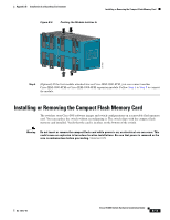
Figure B-9
Stripping the Ground Wire
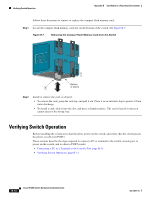
Step 3
Insert the ground wire into the ring terminal lug, and using a crimping tool, crimp the ring terminal to
the wire.
Figure B-10
Crimping the Ring Terminal
Step 4
Slide the ground screw through the ring terminal.
Step 5
Insert the ground screw into the functional ground screw opening on the front panel.
Step 6
Use a ratcheting torque screwdriver to tighten the ground screw and ring terminal lug to the switch front
panel to 8.5 in-lb. See
Figure B-11
.
1
0.5 in. (12.7 mm) ± 0.02 in.
(0.5 mm)
3
Wire lead
2
Insulation
104908
2
1
3
76666