Cisco WS-CBS3020-HPQ Installation Guide - Page 39
Connecting the Protective Ground and DC Power, Grounding the Switch
 |
View all Cisco WS-CBS3020-HPQ manuals
Add to My Manuals
Save this manual to your list of manuals |
Page 39 highlights
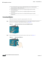
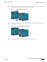
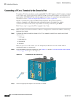
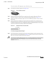
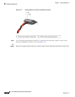
Chapter 2 Switch Installation Verifying Switch Operation Step 5 Connect the other end of the adapter cable to the PC or terminal adapter. Step 6 Start the terminal-emulation software on the PC. Connecting the Protective Ground and DC Power These sections describe the steps required to connect a protective ground and DC power to the switch: • Grounding the Switch, page 2-13 • Wiring the DC Power Source, page 2-16 • Attach the Power and Relay Connector to the Switch, page 2-21 Note The Cisco IE 3000 switch can be used with an optional AC/DC power converter (PWR-IE3000-AC). For instructions on how to connect the power converter to the switch, see the "Connecting the Switch to the Power Converter" section on page 2-44. Locate the power and relay connector in the switch accessory kit. Note You can get replacement power and relay connectors (PWR-IE3000-CNCT=) by calling Cisco Technical Support. See the "Obtaining Documentation, Obtaining Support, and Security Guidelines" section on page x. Obtain these necessary tools and equipment: • Ratcheting torque flathead screwdriver that exerts up to 15 inch-pounds (in-lb) of pressure • Ring terminal lug (such as Thomas & Bett part number 10RCR or equivalent) • Crimping tool (such as Thomas & Bett part number WT2000, ERG-2001, or equivalent) • 10-gauge copper ground wire (such as Belden part number 9912 or equivalent) • For DC power connections, use UL- and CSA-rated, style 1007 or 1569 twisted-pair copper appliance wiring material (AWM) wire (such as Belden part number 9318). • Wire-stripping tools for stripping 10- and 18-gauge wires Grounding the Switch To ground the switch to earth ground by using the ground screw, follow these steps. Make sure to follow any grounding requirements at your site. Warning This equipment must be grounded. Never defeat the ground conductor or operate the equipment in the absence of a suitably installed ground conductor. Contact the appropriate electrical inspection authority or an electrician if you are uncertain that suitable grounding is available. Statement 1024 OL-13017-01 Cisco IE 3000 Switch Hardware Installation Guide 2-13
-
 1
1 -
2
-
3
-
4
-
5
-
6
-
7
-
8
-
9
-
10
-
11
-
12
-
13
-
14
-
15
-
16
-
17
-
18
-
19
-
20
-
21
-
22
-
23
-
24
-
25
-
26
-
27
-
28
-
29
-
30
-
31
-
32
-
33
-
 34
34 -
 35
35 -
 36
36 -
 37
37 -
 38
38 -
 39
39 -
 40
40 -
 41
41 -
 42
42 -
 43
43 -
 44
44 -
45
-
46
-
47
-
48
-
49
-
50
-
51
-
52
-
53
-
54
-
55
-
56
-
57
-
58
-
59
-
60
-
61
-
62
-
63
-
64
-
65
-
66
-
67
-
68
-
69
-
70
-
71
-
72
-
73
-
74
-
75
-
76
-
77
-
78
-
79
-
80
-
81
-
82
-
83
-
84
-
85
-
86
-
87
-
88
-
89
-
90
-
91
-
92
-
93
-
94
-
95
-
96
-
97
-
98
-
99
-
100
-
101
-
102
-
103
-
104
-
105
-
106
-
107
-
108
-
109
-
110
-
111
-
112
-
113
-
114
-
115
-
116
-
117
-
118
-
119
-
120
-
121
-
122
-
123
-
124
-
125
-
126
-
127
-
128
-
129
-
130
-
131
-
132
-
133
-
134
-
135
-
136
-
137
-
138
-
139
-
140
-
141
-
142
-
143
-
144
-
145
-
146
-
147
-
148
-
149
-
150
-
151
-
152
-
153
-
154
-
155
-
156
-
157
-
158
-
159
-
160
-
161
-
162
-
163
-
164
-
165
-
166
-
167
-
168
-
169
-
170
 |
 |
