Cisco WS-CBS3020-HPQ Installation Guide - Page 47
Attach the Power and Relay Connector to the Switch,
 |
View all Cisco WS-CBS3020-HPQ manuals
Add to My Manuals
Save this manual to your list of manuals |
Page 47 highlights
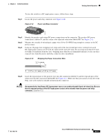
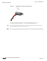
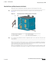
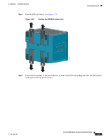
Chapter 2 Switch Installation Verifying Switch Operation Attach the Power and Relay Connector to the Switch Follow these steps to attach the power and relay connectors to the front panel of the switch. Step 1 Insert the power and relay connector into the Pwr A receptacle on the switch front panel. See Figure 2-17. Figure 2-17 1 Connecting the Power and Relay Connector to the Switch 2 V RT A A V RT A A 201858 43 1 Power source A connector 2 Pwr A receptacle 3 Pwr B receptacle 4 Power source B connector Step 2 Use a racheting torque flathead screwdriver to tighten the captive screws on the sides of the power and relay connector. When you are testing the switch, one power source is sufficient. If you are installing the switch and are using a second power source, repeat this procedure for the second power and relay connector (Pwr B), which installs just below the primary power connector (Pwr A). When you are installing the switch, secure the wires coming from the power and relay connector so that they cannot be disturbed by casual contact. For example, use tie wraps to secure the wires to the rack. OL-13017-01 Cisco IE 3000 Switch Hardware Installation Guide 2-21
-
 1
1 -
2
-
3
-
4
-
5
-
6
-
7
-
8
-
9
-
10
-
11
-
12
-
13
-
14
-
15
-
16
-
17
-
18
-
19
-
20
-
21
-
22
-
23
-
24
-
25
-
26
-
27
-
28
-
29
-
30
-
31
-
32
-
33
-
34
-
35
-
36
-
37
-
38
-
39
-
40
-
41
-
 42
42 -
 43
43 -
 44
44 -
 45
45 -
 46
46 -
 47
47 -
 48
48 -
 49
49 -
 50
50 -
 51
51 -
 52
52 -
53
-
54
-
55
-
56
-
57
-
58
-
59
-
60
-
61
-
62
-
63
-
64
-
65
-
66
-
67
-
68
-
69
-
70
-
71
-
72
-
73
-
74
-
75
-
76
-
77
-
78
-
79
-
80
-
81
-
82
-
83
-
84
-
85
-
86
-
87
-
88
-
89
-
90
-
91
-
92
-
93
-
94
-
95
-
96
-
97
-
98
-
99
-
100
-
101
-
102
-
103
-
104
-
105
-
106
-
107
-
108
-
109
-
110
-
111
-
112
-
113
-
114
-
115
-
116
-
117
-
118
-
119
-
120
-
121
-
122
-
123
-
124
-
125
-
126
-
127
-
128
-
129
-
130
-
131
-
132
-
133
-
134
-
135
-
136
-
137
-
138
-
139
-
140
-
141
-
142
-
143
-
144
-
145
-
146
-
147
-
148
-
149
-
150
-
151
-
152
-
153
-
154
-
155
-
156
-
157
-
158
-
159
-
160
-
161
-
162
-
163
-
164
-
165
-
166
-
167
-
168
-
169
-
170
 |
 |