Cisco WS-CBS3020-HPQ Installation Guide - Page 48
Running POST, Power On the Switch, Verify POST Results, Disconnect Power
 |
View all Cisco WS-CBS3020-HPQ manuals
Add to My Manuals
Save this manual to your list of manuals |
Page 48 highlights
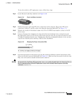
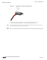
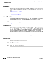
Verifying Switch Operation Chapter 2 Switch Installation Running POST When the switch powers on, it automatically initiates a POST. The POST runs a series of tests that verify that the switch functions properly and ensures that it is ready to install. To test the switch, follow these steps: • Power On the Switch, page 2-22 • Verify POST Results, page 2-22 • Disconnect Power, page 2-22 Power On the Switch To apply power to a switch that is directly connected to a DC power source, locate the circuit breaker on the panel board that services the DC circuit, and switch the circuit breaker to the ON position. Note For instructions on how to apply power to a switch that is connected to a power converter, see the "Applying Power to the Power Converter" section on page 2-53. Verify POST Results When you power on the switch, it automatically begins POST. All LEDs are off for a few seconds, and then each LED is tested. One at a time, the System, Alarm, Setup, Pwr A, and Pwr B LEDs each briefly turn green, then red, and then go off. The System LED blinks green as the boot loader verifies the basic functionality of the processing and memory hardware. Assuming all tests pass, the System LED continues to blink green as the Cisco IOS software image loads. If the POST fails, the System LED turns red. Note POST failures are usually fatal. Call Cisco Systems immediately if your switch does not pass POST. See the "Obtaining Documentation, Obtaining Support, and Security Guidelines" section on page x. Disconnect Power After successfully running POST, follow these steps. Step 1 Step 2 Step 3 Turn off power to the switch. Disconnect the cables. Decide where you want to install the switch. 2-22 Cisco IE 3000 Switch Hardware Installation Guide OL-13017-01
-
 1
1 -
2
-
3
-
4
-
5
-
6
-
7
-
8
-
9
-
10
-
11
-
12
-
13
-
14
-
15
-
16
-
17
-
18
-
19
-
20
-
21
-
22
-
23
-
24
-
25
-
26
-
27
-
28
-
29
-
30
-
31
-
32
-
33
-
34
-
35
-
36
-
37
-
38
-
39
-
40
-
41
-
42
-
 43
43 -
 44
44 -
 45
45 -
 46
46 -
 47
47 -
 48
48 -
 49
49 -
 50
50 -
 51
51 -
 52
52 -
 53
53 -
54
-
55
-
56
-
57
-
58
-
59
-
60
-
61
-
62
-
63
-
64
-
65
-
66
-
67
-
68
-
69
-
70
-
71
-
72
-
73
-
74
-
75
-
76
-
77
-
78
-
79
-
80
-
81
-
82
-
83
-
84
-
85
-
86
-
87
-
88
-
89
-
90
-
91
-
92
-
93
-
94
-
95
-
96
-
97
-
98
-
99
-
100
-
101
-
102
-
103
-
104
-
105
-
106
-
107
-
108
-
109
-
110
-
111
-
112
-
113
-
114
-
115
-
116
-
117
-
118
-
119
-
120
-
121
-
122
-
123
-
124
-
125
-
126
-
127
-
128
-
129
-
130
-
131
-
132
-
133
-
134
-
135
-
136
-
137
-
138
-
139
-
140
-
141
-
142
-
143
-
144
-
145
-
146
-
147
-
148
-
149
-
150
-
151
-
152
-
153
-
154
-
155
-
156
-
157
-
158
-
159
-
160
-
161
-
162
-
163
-
164
-
165
-
166
-
167
-
168
-
169
-
170
 |
 |