Cisco WS-CBS3020-HPQ Installation Guide - Page 69
Connecting to 100BASE-FX Ports
 |
View all Cisco WS-CBS3020-HPQ manuals
Add to My Manuals
Save this manual to your list of manuals |
Page 69 highlights
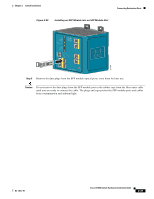
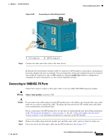
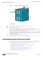
Chapter 2 Switch Installation Figure 2-36 Connecting to a Dual-Purpose Port 1 2 Connecting Destination Ports 201871 1 LC connector 2 RJ-45 connector Step 2 Connect the other end of the cable to the other device. By default, the switch detects whether an RJ-45 connector or SFP module is connected to a dual-purpose port and configures the port accordingly. You can change this setting and configure the port to recognize only an RJ-45 connector or only an SFP module by using the media type interface configuration command. For more information, see the switch command reference. Connecting to 100BASE-FX Ports Follow these steps to connect a fiber-optic cable to an Cisco IEM-3000-8FM expansion module: Warning Class 1 laser product. Statement 1008 Caution Do not remove the rubber plugs from the SFF module port or the rubber caps from the fiber-optic cable until you are ready to connect the cable. The plugs and caps protect the SFF module ports and cables from contamination and ambient light. Before connecting to the SFF module port, be sure that you understand the port and cabling stipulations in the "Preparing for Installation" section on page 2-1. See the "Cable and Adapter Specifications" section on page C-4 for information about the LC connector on the SFF module. Step 1 Remove the rubber plugs from the module port and fiber-optic cable, and store them for future use. Step 2 Insert one end of the fiber-optic cable into the SFP module port. See Figure 2-37. OL-13017-01 Cisco IE 3000 Switch Hardware Installation Guide 2-43
-
 1
1 -
2
-
3
-
4
-
5
-
6
-
7
-
8
-
9
-
10
-
11
-
12
-
13
-
14
-
15
-
16
-
17
-
18
-
19
-
20
-
21
-
22
-
23
-
24
-
25
-
26
-
27
-
28
-
29
-
30
-
31
-
32
-
33
-
34
-
35
-
36
-
37
-
38
-
39
-
40
-
41
-
42
-
43
-
44
-
45
-
46
-
47
-
48
-
49
-
50
-
51
-
52
-
53
-
54
-
55
-
56
-
57
-
58
-
59
-
60
-
61
-
62
-
63
-
 64
64 -
 65
65 -
 66
66 -
 67
67 -
 68
68 -
 69
69 -
 70
70 -
 71
71 -
 72
72 -
 73
73 -
 74
74 -
75
-
76
-
77
-
78
-
79
-
80
-
81
-
82
-
83
-
84
-
85
-
86
-
87
-
88
-
89
-
90
-
91
-
92
-
93
-
94
-
95
-
96
-
97
-
98
-
99
-
100
-
101
-
102
-
103
-
104
-
105
-
106
-
107
-
108
-
109
-
110
-
111
-
112
-
113
-
114
-
115
-
116
-
117
-
118
-
119
-
120
-
121
-
122
-
123
-
124
-
125
-
126
-
127
-
128
-
129
-
130
-
131
-
132
-
133
-
134
-
135
-
136
-
137
-
138
-
139
-
140
-
141
-
142
-
143
-
144
-
145
-
146
-
147
-
148
-
149
-
150
-
151
-
152
-
153
-
154
-
155
-
156
-
157
-
158
-
159
-
160
-
161
-
162
-
163
-
164
-
165
-
166
-
167
-
168
-
169
-
170
 |
 |
