Cisco WS-CBS3020-HPQ Installation Guide - Page 43
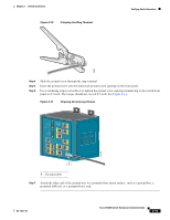
Power and Relay Connector, Stripping the Power Connection Wire
 |
View all Cisco WS-CBS3020-HPQ manuals
Add to My Manuals
Save this manual to your list of manuals |
Page 43 highlights
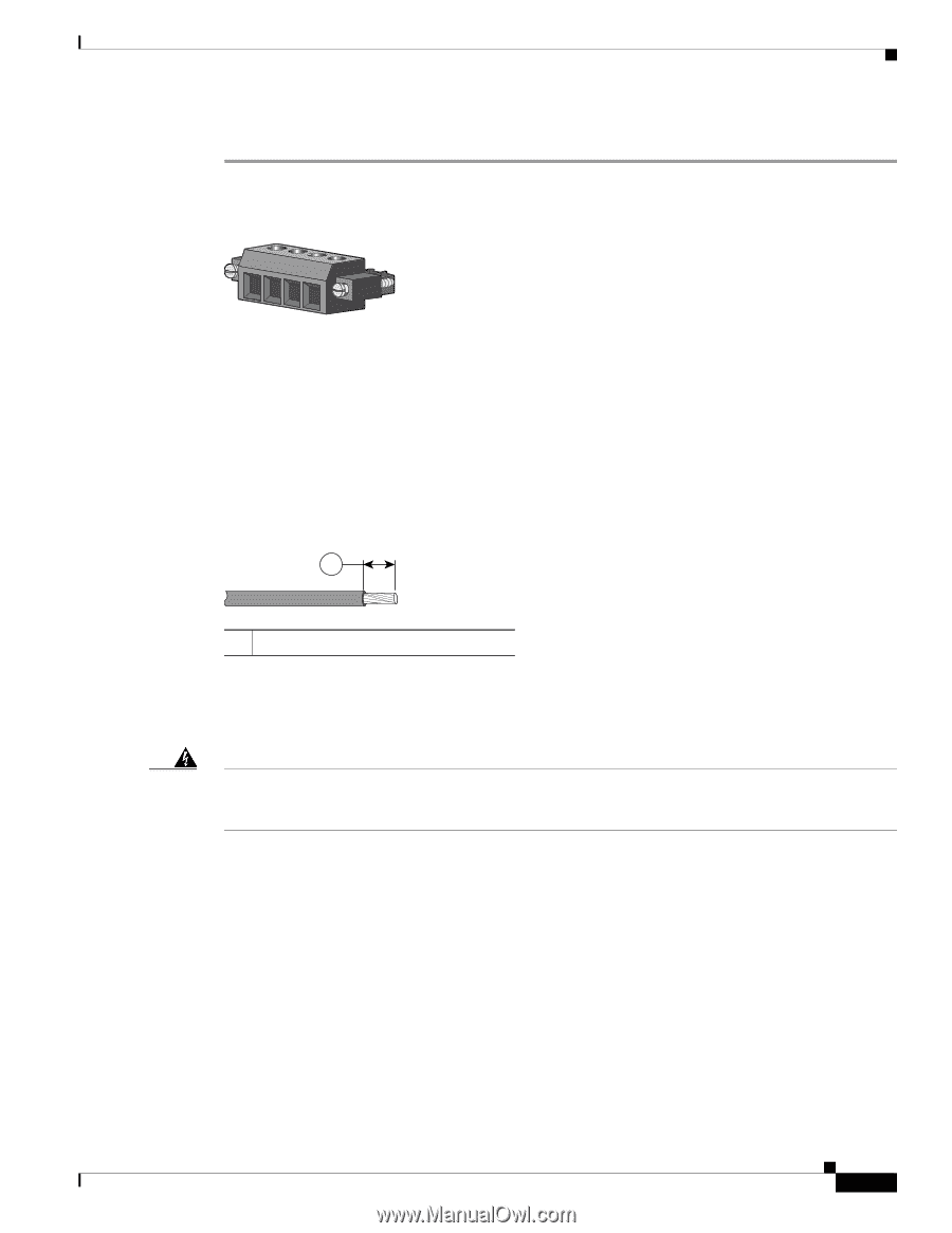
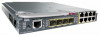
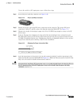
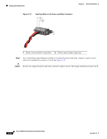
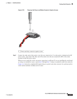
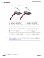
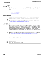
Chapter 2 Switch Installation Verifying Switch Operation To wire the switch to a DC-input power source, follow these steps: Step 1 Locate the power and relay connector (see Figure 2-12). Figure 2-12 Power and Relay Connector V RT A A 201815 Step 2 Step 3 Step 4 Identify the positive and return DC power connections on the connector. The positive DC power connection is labeled V, and the return is the adjacent connection labeled RT. See Figure 2-12. Measure two strands of twisted-pair copper wire (18-to-20 AWG) long enough to connect to the DC power source. Using an 18-gauge wire-stripping tool, strip each of the two twisted pair wires coming from each DC-input power source to 0.25 inch (6.3 mm) ± 0.02 inch (0.5 mm). Do not strip more than 0.27 inch (6.8 mm) of insulation from the wire. Stripping more than the recommended amount of wire can leave exposed wire from the power and relay connector after installation. Figure 2-13 Stripping the Power Connection Wire 1 97489 1 0.25 in. (6.3 mm) ± 0.02 in. (0.5 mm) Step 5 Insert the exposed part of the positive wire into the connection labeled V and the exposed part of the return wire into the connection labeled RT. See Figure 2-14. Make sure that you cannot see any wire lead. Only wire with insulation should extend from the connector. Warning An exposed wire lead from a DC-input power source can conduct harmful levels of electricity. Be sure that no exposed portion of the DC-input power source wire extends from the power and relay connector. Statement 122 OL-13017-01 Cisco IE 3000 Switch Hardware Installation Guide 2-17
-
 1
1 -
2
-
3
-
4
-
5
-
6
-
7
-
8
-
9
-
10
-
11
-
12
-
13
-
14
-
15
-
16
-
17
-
18
-
19
-
20
-
21
-
22
-
23
-
24
-
25
-
26
-
27
-
28
-
29
-
30
-
31
-
32
-
33
-
34
-
35
-
36
-
37
-
 38
38 -
 39
39 -
 40
40 -
 41
41 -
 42
42 -
 43
43 -
 44
44 -
 45
45 -
 46
46 -
 47
47 -
 48
48 -
49
-
50
-
51
-
52
-
53
-
54
-
55
-
56
-
57
-
58
-
59
-
60
-
61
-
62
-
63
-
64
-
65
-
66
-
67
-
68
-
69
-
70
-
71
-
72
-
73
-
74
-
75
-
76
-
77
-
78
-
79
-
80
-
81
-
82
-
83
-
84
-
85
-
86
-
87
-
88
-
89
-
90
-
91
-
92
-
93
-
94
-
95
-
96
-
97
-
98
-
99
-
100
-
101
-
102
-
103
-
104
-
105
-
106
-
107
-
108
-
109
-
110
-
111
-
112
-
113
-
114
-
115
-
116
-
117
-
118
-
119
-
120
-
121
-
122
-
123
-
124
-
125
-
126
-
127
-
128
-
129
-
130
-
131
-
132
-
133
-
134
-
135
-
136
-
137
-
138
-
139
-
140
-
141
-
142
-
143
-
144
-
145
-
146
-
147
-
148
-
149
-
150
-
151
-
152
-
153
-
154
-
155
-
156
-
157
-
158
-
159
-
160
-
161
-
162
-
163
-
164
-
165
-
166
-
167
-
168
-
169
-
170
 |
 |