Cisco WS-CBS3020-HPQ Installation Guide - Page 49
Installing the Switch, Installing the Switch on a DIN Rail
 |
View all Cisco WS-CBS3020-HPQ manuals
Add to My Manuals
Save this manual to your list of manuals |
Page 49 highlights
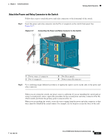
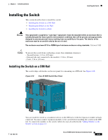
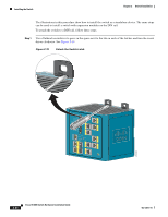
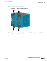
Chapter 2 Switch Installation Installing the Switch Installing the Switch This section describes how to install the switch: • Installing the Switch on a DIN Rail • Installing the Switch on the Wall • Installing the Switch in a Rack Warning This equipment is supplied as "open type" equipment. It must be mounted within an enclosure that is suitably designed for those specific environmental conditions that will be present and appropriately designed to prevent personal injury resulting from accessibility to live parts. The interior of the enclosure must be accessible only by the use of a tool. The enclosure must meet IP 54 or NEMA type 4 minimum enclosure rating standards. Statement 1063 Caution To prevent the switch from overheating, ensure these minimum clearances: - Top and bottom: 4.13 in. (105 mm) - Exposed side (not connected to the module): 3.54 in. (90 mm) - Front: 2.56 in. (65 mm) Installing the Switch on a DIN Rail The switch ships with latches on the rear panel for a mounting on a DIN rail. See Figure 2-18. Figure 2-18 Cisco IE 3000 Switch Rear Panel 203976 OL-13017-01 You can install the switch as a standalone device on the DIN rail or with the expansion modules already connected. You must connect expansion modules to the switch before installing the switch on the DIN rail. To connect the modules to the switch, follow the steps described in the "Adding Modules to the Switch" section on page 2-5. Cisco IE 3000 Switch Hardware Installation Guide 2-23
-
 1
1 -
2
-
3
-
4
-
5
-
6
-
7
-
8
-
9
-
10
-
11
-
12
-
13
-
14
-
15
-
16
-
17
-
18
-
19
-
20
-
21
-
22
-
23
-
24
-
25
-
26
-
27
-
28
-
29
-
30
-
31
-
32
-
33
-
34
-
35
-
36
-
37
-
38
-
39
-
40
-
41
-
42
-
43
-
 44
44 -
 45
45 -
 46
46 -
 47
47 -
 48
48 -
 49
49 -
 50
50 -
 51
51 -
 52
52 -
 53
53 -
 54
54 -
55
-
56
-
57
-
58
-
59
-
60
-
61
-
62
-
63
-
64
-
65
-
66
-
67
-
68
-
69
-
70
-
71
-
72
-
73
-
74
-
75
-
76
-
77
-
78
-
79
-
80
-
81
-
82
-
83
-
84
-
85
-
86
-
87
-
88
-
89
-
90
-
91
-
92
-
93
-
94
-
95
-
96
-
97
-
98
-
99
-
100
-
101
-
102
-
103
-
104
-
105
-
106
-
107
-
108
-
109
-
110
-
111
-
112
-
113
-
114
-
115
-
116
-
117
-
118
-
119
-
120
-
121
-
122
-
123
-
124
-
125
-
126
-
127
-
128
-
129
-
130
-
131
-
132
-
133
-
134
-
135
-
136
-
137
-
138
-
139
-
140
-
141
-
142
-
143
-
144
-
145
-
146
-
147
-
148
-
149
-
150
-
151
-
152
-
153
-
154
-
155
-
156
-
157
-
158
-
159
-
160
-
161
-
162
-
163
-
164
-
165
-
166
-
167
-
168
-
169
-
170
 |
 |
