Compaq Armada m300 Compaq Armada M300 Series of Personal Computers Maintenance - Page 82
Top Cover with TouchPad,
 |
View all Compaq Armada m300 manuals
Add to My Manuals
Save this manual to your list of manuals |
Page 82 highlights
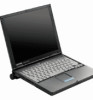
5.15 Top Cover with TouchPad NOTE: The power button and infrared lens are easily dislodged when the top cover is removed. Make note of their location and orientation before removing the top cover. 1. Prepare the computer for disassembly (Figure 5.5). 2. Remove the keyboard (Section 5.11). 3. Remove the switch cover (Section 5.13). 4. Remove the display assembly (Section 5.14). 5. Turn the computer upside down with the rear panel facing forward. 6. Remove the seven screws from the bottom of the computer (Figure 5-21). 7. Remove the four screws from the back of the computer. Figure 5-21. Removing the Top Cover Screws Removal and Replacement Procedures 5-23
-
 1
1 -
2
-
3
-
4
-
5
-
6
-
7
-
8
-
9
-
10
-
11
-
12
-
13
-
14
-
15
-
16
-
17
-
18
-
19
-
20
-
21
-
22
-
23
-
24
-
25
-
26
-
27
-
28
-
29
-
30
-
31
-
32
-
33
-
34
-
35
-
36
-
37
-
38
-
39
-
40
-
41
-
42
-
43
-
44
-
45
-
46
-
47
-
48
-
49
-
50
-
51
-
52
-
53
-
54
-
55
-
56
-
57
-
58
-
59
-
60
-
61
-
62
-
63
-
64
-
65
-
66
-
67
-
68
-
69
-
70
-
71
-
72
-
73
-
74
-
75
-
76
-
 77
77 -
 78
78 -
 79
79 -
 80
80 -
 81
81 -
 82
82 -
 83
83 -
 84
84 -
 85
85 -
 86
86 -
 87
87 -
88
-
89
-
90
-
91
-
92
-
93
-
94
-
95
-
96
-
97
-
98
-
99
-
100
-
101
-
102
 |
 |

Removal and Replacement Procedures
5-23
5.15
Top Cover with TouchPad
NOTE:
The power button and infrared lens are easily dislodged when the top cover is
removed. Make note of their location and orientation before removing the top cover.
1.
Prepare the computer for disassembly (Figure 5.5).
2.
Remove the keyboard (Section 5.11).
3.
Remove the switch cover (Section 5.13).
4.
Remove the display assembly (Section 5.14).
5.
Turn the computer upside down with the rear panel facing forward.
6.
Remove the seven screws from the bottom of the computer (Figure 5-21).
7.
Remove the four screws from the back of the computer.
Figure 5-21.
Removing the Top Cover Screws