D-Link 1824i User Guide - Page 5
About This Guide, Displaying Segment, Group, and Port Statistics
 |
UPC - 790069210358
View all D-Link 1824i manuals
Add to My Manuals
Save this manual to your list of manuals |
Page 5 highlights
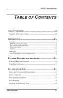
10BASE-T Stackable Hubs Hub Stack Configuration 6-16 Primary and Backup Master Hubs 6-16 Controlling Hubs in the Hub Stack 6-17 Controlling Individual Ports 6-19 Segmenting Hubs 6-23 Monitoring the Hub Stack 6-24 Displaying Segment, Group, and Port Statistics 6-21 Displaying Node Tracking Information 6-28 Resetting the Hub 6-29 System Reset 6-29 Factory Reset 6-30 A SPECIFICATIONS A-1 B POWER-ON SELF TEST B-1 C BOOT CONFIGURATION FILE C-1 D CABLES AND CONNECTORS D-1 Crossover Cable D-2 Daisy-chain Cable D-3 RS-232 (DB9) Pin Specification D-3 0 Table of Contents v
-
 1
1 -
 2
2 -
 3
3 -
 4
4 -
 5
5 -
 6
6 -
 7
7 -
 8
8 -
 9
9 -
 10
10 -
 11
11 -
12
-
13
-
14
-
15
-
16
-
17
-
18
-
19
-
20
-
21
-
22
-
23
-
24
-
25
-
26
-
27
-
28
-
29
-
30
-
31
-
32
-
33
-
34
-
35
-
36
-
37
-
38
-
39
-
40
-
41
-
42
-
43
-
44
-
45
-
46
-
47
-
48
-
49
-
50
-
51
-
52
-
53
-
54
-
55
-
56
-
57
-
58
-
59
-
60
-
61
-
62
-
63
-
64
-
65
-
66
-
67
-
68
-
69
-
70
-
71
-
72
-
73
-
74
-
75
-
76
-
77
-
78
-
79
-
80
-
81
-
82
-
83
-
84
-
85
-
86
-
87
 |
 |

10BASE-T Stackable Hubs
Hub Stack Configuration
......................................................................
6-16
Primary and Backup Master Hubs
..................................................................
6-16
Controlling Hubs in the Hub Stack
................................................................
6-17
Controlling Individual Ports
...........................................................................
6-19
Segmenting Hubs
...........................................................................................
6-23
Monitoring the Hub Stack
....................................................................
6-24
Displaying Segment, Group, and Port Statistics
.............................................
6-21
Displaying Node Tracking Information
.........................................................
6-28
Resetting the Hub
.................................................................................
6-29
System Reset
..................................................................................................
6-29
Factory Reset
..................................................................................................
6-30
A
S
PECIFICATIONS
..........................................................
A-1
B
P
OWER
-O
N
S
ELF
T
EST
................................................
B-1
C
B
OOT
C
ONFIGURATION
F
ILE
.........................................
C-1
D
C
ABLES AND
C
ONNECTORS
..........................................
D-1
Crossover Cable
....................................................................................
D-2
Daisy-chain Cable
.................................................................................
D-3
RS-232 (DB9) Pin Specification
............................................................
D-3
0
Table of Contents
v