D-Link DES-3550 Product Manual - Page 138
Time Range Settings, IP-MAC Binding, ACL Mode
 |
UPC - 790069266317
View all D-Link DES-3550 manuals
Add to My Manuals
Save this manual to your list of manuals |
Page 138 highlights
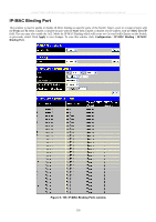
xStack® DES-3500 Series Layer 2 Stackable Fast Ethernet Managed Switch User Manual Time Range Settings The Time Range window is used in conjunction with the Access Profile feature to determine a starting point and an ending point, based on days of the week, and when an Access Profile configuration will be enabled on the Switch. Once configured here, the time range settings are to be applied to an access profile rule using the Access Profile table. The user may enter up to 64 time range entries on the Switch. To open this window, click Configuration > Time Range Settings: Figure 6- 99. Time Range Settings window To delete an entry click the corresponding , to view a previously configured time range entry click will be displayed. the following window Figure 6- 100. Time Range Settings window - View To return to the Time Range Configuration window, click the hyperlinked Return to Time Range Settings. IP-MAC Binding The IP network layer uses a four-byte address. The Ethernet link layer uses a six-byte MAC address. Binding these two address types together allows the transmission of data between the layers. The primary purpose of IP-MAC binding is to restrict the access to a switch to a number of authorized users. Only the authorized client can access the Switch's port by checking the pair of IPMAC addresses with the pre-configured database. If an unauthorized user tries to access an IP-MAC binding enabled port, the system will block the access by dropping its packet. The maximum number of IP-MAC binding entries is dependant on chip capability (e.g. the ARP table size) and storage size of the device. For the xStack® DES-3500 Series switches, the maximum number of IP-MAC Binding entries is 512. The creation of authorized users can be manually configured by CLI or Web. The function is port-based, meaning a user can enable or disable the function on the individual port. ACL Mode Due to some special cases that have arisen with the IP-MAC binding, this Switch has been equipped with a special ACL Mode for IP-MAC Binding, which should alleviate this problem for users. When enabled in the IP-MAC Binding Port window, the Switch will create two entries in the Access Profile Table as shown below. The entries may only be created if there are at least two Access Profile IDs available on the Switch. If not, when the ACL Mode is enabled, an error message will be prompted to the user. When the ACL Mode is enabled, the Switch will only accept IP packets from a created entry in the IP-MAC Binding Setting window. All others will be discarded. 123
-
 1
1 -
2
-
3
-
4
-
5
-
6
-
7
-
8
-
9
-
10
-
11
-
12
-
13
-
14
-
15
-
16
-
17
-
18
-
19
-
20
-
21
-
22
-
23
-
24
-
25
-
26
-
27
-
28
-
29
-
30
-
31
-
32
-
33
-
34
-
35
-
36
-
37
-
38
-
39
-
40
-
41
-
42
-
43
-
44
-
45
-
46
-
47
-
48
-
49
-
50
-
51
-
52
-
53
-
54
-
55
-
56
-
57
-
58
-
59
-
60
-
61
-
62
-
63
-
64
-
65
-
66
-
67
-
68
-
69
-
70
-
71
-
72
-
73
-
74
-
75
-
76
-
77
-
78
-
79
-
80
-
81
-
82
-
83
-
84
-
85
-
86
-
87
-
88
-
89
-
90
-
91
-
92
-
93
-
94
-
95
-
96
-
97
-
98
-
99
-
100
-
101
-
102
-
103
-
104
-
105
-
106
-
107
-
108
-
109
-
110
-
111
-
112
-
113
-
114
-
115
-
116
-
117
-
118
-
119
-
120
-
121
-
122
-
123
-
124
-
125
-
126
-
127
-
128
-
129
-
130
-
131
-
132
-
 133
133 -
 134
134 -
 135
135 -
 136
136 -
 137
137 -
 138
138 -
 139
139 -
 140
140 -
 141
141 -
 142
142 -
 143
143 -
144
-
145
-
146
-
147
-
148
-
149
-
150
-
151
-
152
-
153
-
154
-
155
-
156
-
157
-
158
-
159
-
160
-
161
-
162
-
163
-
164
-
165
-
166
-
167
-
168
-
169
-
170
-
171
-
172
-
173
-
174
-
175
-
176
-
177
-
178
-
179
-
180
-
181
-
182
-
183
-
184
-
185
-
186
-
187
-
188
-
189
-
190
-
191
-
192
-
193
-
194
-
195
-
196
-
197
-
198
-
199
-
200
-
201
-
202
-
203
-
204
-
205
-
206
-
207
-
208
-
209
-
210
-
211
-
212
-
213
-
214
-
215
-
216
-
217
-
218
-
219
-
220
-
221
-
222
-
223
-
224
-
225
-
226
-
227
-
228
-
229
-
230
-
231
-
232
-
233
-
234
-
235
-
236
-
237
-
238
-
239
-
240
-
241
-
242
-
243
-
244
-
245
-
246
-
247
-
248
-
249
-
250
-
251
-
252
-
253
-
254
-
255
-
256
-
257
-
258
-
259
-
260
-
261
-
262
-
263
-
264
-
265
-
266
-
267
-
268
-
269
-
270
-
271
-
272
-
273
-
274
-
275
-
276
-
277
-
278
-
279
-
280
-
281
-
282
-
283
-
284
-
285
-
286
-
287
-
288
-
289
-
290
-
291
-
292
-
293
-
294
-
295
-
296
-
297
-
298
-
299
-
300
-
301
-
302
-
303
-
304
-
305
-
306
-
307
-
308
-
309
-
310
-
311
-
312
-
313
-
314
-
315
-
316
-
317
-
318
-
319
-
320
-
321
-
322
-
323
-
324
-
325
-
326
-
327
-
328
 |
 |
