| Section |
Page |
| Dell 5110cn Service Manual - Introduction |
1 |
| Copyright notice |
2 |
| Cautions for operation |
3 |
| 1. About this manual |
4 |
| 2. Marks giving caution |
4 |
| 3. Related documents |
4 |
| 4. Safety |
5 |
| 4.1 Power source |
5 |
| 4.2 Driving units |
6 |
| 4.3 High-temperature units |
6 |
| 4.4 Laser beams |
7 |
| 4.5 Warning/caution labels |
8 |
| 4.5.1 Caution label for high-temperature units |
8 |
| 4.5.2 Caution label regarding toner cartridge |
8 |
| 4.5.3 Caution label regarding Imaging Drum and Transfer Roller |
9 |
| 4.5.4 Caution label regarding MPF and paper tray |
10 |
| 4.5.5 Caution label regarding Developer Frame |
10 |
| 4.5.6 Caution label regarding Print Head |
11 |
| Unpacking the Printer |
12 |
| Table of Contents |
13 |
| Dell 5110cn Service Manual - Chapter 1 Troubleshooting |
14 |
| Contents |
14 |
| 1. Progressing with the Troubleshooting |
18 |
| 1.1 Flow of Troubleshooting |
18 |
| 1.2 Preparatory Requirements |
19 |
| 1.3 Cautions for Service Operations |
20 |
| 1.4 Cautions for FIP Use |
21 |
| 2. Level 1 FIP |
23 |
| 2.1 Level 1 FIP |
23 |
| 2.2 Flow of Level 1 FIP |
23 |
| 3. Level 2 FIP |
25 |
| 3.1 Level 2 FIP |
25 |
| 3.2 Status Code List |
26 |
| 3.3 LCD Display |
32 |
| 3.4 Error Code FIP |
42 |
| FIP-1 001-360/001-363/001-364/001-366 Restart Printer |
42 |
| FIP-2 001-361/001-363/001-365/001-366 Restart Printer |
43 |
| FIP-3 001-362/001-364/001-365/001-366 Restart Printer |
44 |
| FIP-4 003-340/003-341/003-342/003-344/003-345/003-346/003-347/003-348/003-349/ 003-350/003-351 Re... |
45 |
| FIP-5 003-343 Restart Printer |
46 |
| FIP-6 003-356 Restart Printer |
48 |
| FIP-7 004-310 Restart Printer |
51 |
| FIP-8 006-370/006-371/006-372/006-373/006-374/006-375/006-376/006-377/006-378/ 006-379/006-380/00... |
52 |
| FIP-9 007-342/007-345/007-346/007-348 Restart Printer |
53 |
| FIP-10 007-343/007-345/007-347/007-348 Restart Printer |
54 |
| FIP-11 007-344/007-346/007-347/007-348 Restart Printer |
55 |
| FIP-12 009-340/009-341 Restart Printer |
56 |
| FIP-13 009-360/009-361/009-362/009-363 Restart Printer |
57 |
| FIP-14 010-354 Restart Printer |
58 |
| FIP-15 010-378/010-379/010-380/010-381/010-382/010-383/010-384/010-385/010-386/ 010-387/010-388/0... |
59 |
| FIP-16 016-300/016-301/016-302/016-310/016-311/016-313/016-315/016-317/016-323/ 016-324/016-327/0... |
60 |
| FIP-17 016-312 Restart Printer |
61 |
| FIP-18 016-316/016-318 Restart Printer |
62 |
| FIP-19 016-330/016-331/016-332/016-333/016-334/016-335/016-336/016-337 Restart Printer |
63 |
| FIP-20 016-338 Restart Printer |
65 |
| FIP-21 016-350 Restart Printer |
66 |
| FIP-22 016-360/016-361 Restart Printer |
67 |
| FIP-23 016-370 Restart Printer |
68 |
| FIP-24 Paper Jam 077-902 |
69 |
| FIP-25 Paper Jam 077-900 |
70 |
| FIP-26 Paper Jam 071-101 |
71 |
| FIP-27 Paper Jam 077-907 |
77 |
| FIP-28 Load Tray N 024-910/024-911/024-912/024-913/024-914 |
78 |
| FIP-29 Exit Tray Full 024-920 |
79 |
| FIP-30 Load MPF 024-969/Load Tray N 024-965/024-966/024-967/024-968/024-969 |
80 |
| FIP-31 Tape On XXX Toner 093-919/093-920/093-921/093-922 |
83 |
| FIP-32 Insert TonerCart 093-970 |
84 |
| FIP-33 Insert TonerCart 093-971 |
85 |
| FIP-34 Insert TonerCart 093-972 |
86 |
| FIP-35 Insert TonerCart 093-973 |
87 |
| FIP-36 Replace Toner 093-930 |
88 |
| FIP-37 Replace Toner 093-931 |
89 |
| FIP-38 Replace Toner 093-932 |
90 |
| FIP-39 Replace Toner 093-933 |
91 |
| FIP-40 Ready to Print 093-423 |
92 |
| FIP-41 Ready to Print 093-424 |
93 |
| FIP-42 Ready to Print 093-425 |
94 |
| FIP-43 Ready to Print 093-426 |
95 |
| FIP-44 Toner Type 093-980/093-981/093-982/093-983/CRUM ID 093-960/093-961/ 093-962/093-963 |
96 |
| FIP-45 Insert Drum 091-972 |
98 |
| FIP-46 Imaging Drum 091-935 |
99 |
| FIP-47 Ready to Print 094-402 |
100 |
| FIP-48 Imaging Drum 091-912/CRUM ID 093-965 |
101 |
| FIP-49 Replace Fuser 010-351 |
102 |
| FIP-50 Insert Fuser 010-317 |
103 |
| FIP-51 Ready to Print 010-421 |
104 |
| FIP-52 Fuser Type 010-358/CRUM ID 093-964 |
105 |
| FIP-53 Transfer Roller 094-911 |
106 |
| FIP-54 Ready to Print 094-422 |
107 |
| FIP-55 BTR Not Detected 094-910 |
108 |
| FIP-56 Load Tray N 077-912/077-913/077-914/Tray Detached 024-945/024-946/024-947/ 024-948/024-949 |
109 |
| FIP-57 Close Front Door 077-300 |
110 |
| FIP-58 CTD Sensor Dirty 092-310/Ready to Print 092-910 |
112 |
| FIP-59 Out of Memory 016-700 |
114 |
| FIP-60 Disk Full 016-980 |
115 |
| FIP-61 PCL Request 016-720 |
117 |
| FIP-62 Invalid Job 016-799 |
118 |
| FIP-63 Ready to Print 193-700 |
119 |
| FIP-64 Invalid ID 016-383/Range Chk Error 016-384/Header Error 016-385/ Check Sum Error 016-386/F... |
120 |
| FIP-65 MPC Error 016-388/MPC Detached 016-389/MPC Com. Failed 016-390 |
121 |
| FIP-66 Invalid User 016-757/Disabled Func 016-758/Reached Limits 016-759 |
123 |
| 3.5 Image Quality Troubleshooting |
124 |
| P1 \ |
130 |
| P2 \ |
133 |
| P3 \ |
135 |
| P4 \ |
136 |
| P5 \ |
139 |
| P6 \ |
142 |
| P7 \ |
145 |
| P8 \ |
147 |
| P9 \ |
151 |
| P10 \ |
156 |
| P11 \ |
157 |
| P12 \ |
158 |
| P13 \ |
159 |
| P14 \ |
160 |
| P15 \ |
162 |
| P16 \ |
164 |
| 3.6 Other FIP |
167 |
| FIP-No Power |
167 |
| FIP-Multiple Feed |
168 |
| 4. Abnormal Noise Trouble |
169 |
| 4.1 Entry Chart for Abnormal Noise Troubleshooting |
169 |
| 4.2 Operation Mode Table |
170 |
| FIP-1.N1 When Power is Turned On |
170 |
| FIP-1.N2 During Standby |
171 |
| FIP-1.N3 During Printing |
172 |
| Dell 5110cn Service Manual - Chapter 2 Operation of Diagnostics |
177 |
| Contents |
177 |
| 1. Overview |
179 |
| 1.1 Position of the Diag. in the Whole System |
179 |
| 2. Configuration |
180 |
| 3. How to use Diag. Customer Mode |
181 |
| 3.1 Roles of the control panel in Diag. |
181 |
| 3.2 Entering diag. Customer mode |
182 |
| 3.3 Selecting Diag. item |
182 |
| 3.4 Change method parameters value |
182 |
| 3.5 Executing/Exiting Diag. mode |
182 |
| 3.6 Diag. mode menu tree |
183 |
| 4. The Kind of Diag. and Contents of a Test |
185 |
| 4.1 Details of ESS diagnosis |
189 |
| 4.1.1 Executing ESS diagnosis |
189 |
| 4.1.2 All Test |
189 |
| 4.1.3 CodeROM Test |
189 |
| 4.1.4 FontROM Test |
189 |
| 4.1.5 EEPROM Test |
190 |
| 4.1.6 DRAM Test |
190 |
| 4.1.7 MAC+PHY Test |
191 |
| 4.1.8 ASIC Test |
191 |
| 4.1.9 PANEL Test |
191 |
| 4.1.10 IOT Test |
191 |
| 4.1.11 HD Test |
191 |
| 4.2 IOT Diag. |
192 |
| 4.2.1 Digital Input (DI) Test |
192 |
| 4.2.2 Executing digital input (DI) test |
192 |
| 4.2.3 Exiting digital input (DI) test |
194 |
| 4.2.4 How to check sensors and switches |
194 |
| 4.2.5 Digital Output (DO) Test |
212 |
| 4.2.6 Executing digital output (DO) test |
212 |
| 4.2.7 Exiting digital output (DO) test |
216 |
| 4.2.8 How to check the motors, clutches and solenoids |
216 |
| 4.3 Test Print |
239 |
| 4.3.1 Executing test print |
239 |
| 4.3.2 No Image [IOT] |
239 |
| 4.3.3 Test Pattern 600[IOT] |
239 |
| 4.3.4 Grid2 |
240 |
| 4.3.5 20% Density Chart |
240 |
| 4.3.6 Gradation |
242 |
| 4.3.7 Toner Pallet Check |
242 |
| 4.3.8 Contamination Check |
243 |
| 4.4 Parameter Setting |
244 |
| 4.4.1 Handling parameters |
244 |
| 4.4.2 Printing the parameter list |
246 |
| Dell 5110cn Service Manual - Chapter 3 Removal and Replacement Procedures (RRPs) |
247 |
| Contents |
247 |
| 1. Removal and Replacement Procedures (RRPs) |
251 |
| 1.1 Before starting service work |
251 |
| 1.2 Description of procedure |
254 |
| 2. Removal and Replacement Flows |
256 |
| RRP1. COVER |
264 |
| RRP1.1 TOP COVER FRAME (PL1.1.4) |
264 |
| RRP1.2 OPERATOR PANEL (PL1.1.5) |
266 |
| RRP1.3 FRONT COVER (PL1.1.6) |
268 |
| RRP1.4 IMAGING DRUM COVER (PL1.1.8), IMAGING DRUM COVER HINGE PIN (PL1.1.21) |
270 |
| RRP1.5 COVER ASSY REAR (PL1.1.17) |
272 |
| RRP1.6 REAR FAN (PL1.1.19) |
274 |
| RRP1.7 RIGHT SIDE COVER (PL1.1.20) |
276 |
| RRP1.8 RIGHT FRONT COVER (PL1.1.22) |
278 |
| RRP1.9 MULTIPURPOSE FEEDER (MPF) TRAY (PL1.1.23) |
280 |
| RRP1.10 MULTIPURPOSE FEEDER (MPF) COVER (PL1.1.25) |
282 |
| RRP1.11 LEFT FRONT COVER (PL1.1.28) |
284 |
| RRP1.12 LEFT SIDE COVER (PL1.1.30) |
286 |
| RRP1.13 FAN LV (PL1.1.33) |
288 |
| RRP1.14 REAR COVER (PL1.1.18) |
290 |
| RRP2. PAPER CASSETTE |
292 |
| RRP2.1 SEPARATOR ROLLER. (PL2.1.13), SEPARATOR ROLLER CLUTCH (PL2.1.14) |
292 |
| RRP2.2 RETARD ASSY (PL2.1.12) |
294 |
| RRP3. PAPER FEEDER |
296 |
| RRP3.1 PAPER FEEDER CHUTE. (PL3.1.2) |
296 |
| RRP3.2 PAPER TRAY COVER (PL3.1.3) |
298 |
| RRP3.3 PAPER FEEDER (PL3.1.7) |
300 |
| RRP3.4 SWITCH ASSY SIZE (PL3.2.5) |
304 |
| RRP3.5 SWITCH (PL3.2.10) |
306 |
| RRP3.6 HARNESS ASSY OPFPLG (PL3.2.11) |
308 |
| RRP3.7 PAPER PICKUP ASSEMBLY (PL3.3.1) |
310 |
| RRP3.8 ROLL ASSY TURN (PL3.3.2) |
312 |
| RRP3.9 SENSOR PHOTO: NO PAPER (PL3.3.7) |
314 |
| RRP3.10 Blank Page |
316 |
| RRP3.11 SOLENOID FEED (PL3.3.11) |
318 |
| RRP3.12 Blank Page |
320 |
| RRP3.13 CHUTE UPPER (REFERENCE ONLY) |
322 |
| RRP3.14 PAPER FEED ROLLER (PL3.3.18) |
324 |
| RRP3.15 ACTUATOR NO PAPER (PL3.3.20) |
326 |
| RRP4. RETARD & REGI ASSY |
328 |
| RRP4.1 ACTUATOR REGI (PL4.1.1) |
328 |
| RRP4.2 REGISTRATION SENSOR (PL.4.1.3) |
330 |
| RRP4.3 REGISTRATION CHUTE ASSEMBLY (PL4.1.20) |
332 |
| RRP4.4 Blank Page |
334 |
| RRP4.5 MULTIPURPOSE FEEDER (MPF) SEPARATOR ASSEMBLY (PL4.1.13), MULTIPURPOSE FEEDER (MPF) SEPARAT... |
336 |
| RRP4.6 REGISTRATION ASSEMBLY (PL4.2.1) |
338 |
| RRP4.7 ROLL REGI METAL. (PL4.2.3) |
340 |
| RRP4.8 ROLL REGI RUBBER. (PL4.2.4) |
342 |
| RRP4.9 CLUTCH REGI. (PL4.2.7) |
344 |
| RRP4.10 CLUTCH TURN. (PL4.2.9) |
346 |
| RRP4.11 ROLL TURN MSI. (PL4.2.10) |
348 |
| RRP5. CHUTE ASSY IN & OUT |
350 |
| RRP5.1 FUSER. (PL5.1.1) |
350 |
| RRP5.2 TRANSFER ROLLER. (PL5.1.4) |
352 |
| RRP5.3 AUTOMATIC DENSITY CONTROL (ADC) SENSOR. (PL5.2.19) |
354 |
| RRP5.4 TONER FULL SENSOR (PL5.2.20) |
356 |
| RRP5.5 DRIVE ASSY FUSER (PL5.2.25) |
358 |
| RRP5.6 MULTIPURPOSE FEEDER (MPF) SOLENOID. (PL5.3.9) |
362 |
| RRP5.7 MULTIPURPOSE FEEDER (MPF) PAPER SENSOR (PL5.3.14) |
366 |
| RRP5.8 MULTIPURPOSE FEEDER (MPF) ACTUATOR (PL.5.3.15) |
368 |
| RRP5.9 MULTIPURPOSE FEEDER (MPF) ROLLER (PL.5.3.20) |
370 |
| RRP5.10 OUTPUT TRAY FULL SENSOR (PL5.4.1) |
374 |
| RRP5.11 SENSOR PHOTO: JAM (PL5.4.1) |
376 |
| RRP5.12 OUTPUT TRAY ACTUATOR (PL5.4.2) |
380 |
| RRP5.13 DUPLEX DRIVE MOTOR (PL5.4.5) |
382 |
| RRP5.14 ACTUATOR DUP (PL5.4.13) |
384 |
| RRP5.15 ROLL DUP (PL5.4.15) |
386 |
| RRP5.16 ROLL EXIT (PL5.4.16) |
388 |
| RRP5.17 INNER DUPLEX ASSEMBLY (PL5.2.1), DUPLEX HINGE LINK SPRING (PL5.1.6), DUPULEX HINGE LINK (... |
390 |
| RRP5.18 OUTER DUPLEX ASSEMBLY (PL5.3.1), DUPLEX RETAINING STRAP (PL5.1.5) |
394 |
| RRP5.19 FAN FRONT (PL5.3.31) |
398 |
| RRP6. XEROGRAPHICS |
400 |
| RRP6.1 PRINT HEAD (PL6.1.2) |
400 |
| RRP6.2 HSG ASSY BIAS (PL6.1.7) |
402 |
| RRP7. DEVELOPMENT |
404 |
| RRP7.1 DEVELOPER FRAME (PL7.1.1) |
404 |
| RRP7.2 CRUM (PL7.1.4) |
406 |
| RRP7.3 DEVELOPER ASSEMBLY (Y), (M), (C), (K) (PL7.1.17~20) |
408 |
| RRP7.4 TONER DISPENSER ASSEMBLY (PL7.2.22) |
410 |
| RRP7.5 DISPENSER ASSY (Y) (PL7.2.1) |
414 |
| RRP7.6 DISPENSER ASSY (M) (PL7.2.2) |
416 |
| RRP7.7 DISPENSER ASSY (C) (PL7.2.3) |
418 |
| RRP7.8 DISPENSER ASSY (K) (PL7.2.4) |
420 |
| RRP7.9 SENSOR NO TONER (Y), (M), (C) (PL7.2.5) |
422 |
| RRP7.10 SENSOR NO TONER (K) (PL7.2.5) |
424 |
| RRP7.11 ACTUATOR SENSOR 2 (PL7.2.7) |
426 |
| RRP7.12 TONER CARTRIDGE SENSOR (PL7.2.12) |
428 |
| RRP7.13 DUCT LV (PL7.2.23) |
430 |
| RRP8. DRIVE |
432 |
| RRP8.1 DEVELOPER DRIVE ASSEMBLY (PL8.1.1) |
432 |
| RRP8.2 MAIN DRIVE ASSEMBLY (PL8.1.2) |
436 |
| RRP9. ELECTRICAL |
438 |
| RRP9.1 CONTROLLER CARD (PL9.1.3) |
438 |
| RRP9.2 LVPS ASSY (REFERENCE ONLY) |
442 |
| RRP9.3 LOW VOLTAGE POWER SUPPLY (LVPS) (PL9.1.6) |
444 |
| RRP9.4 HARNESS ASSY AC INLET (PL9.1.7) |
446 |
| RRP9.5 HARNESS ASSY INTERLOCK (PL9.1.11) |
448 |
| RRP9.6 PWBA EEPROM STD (PL9.1.12) |
450 |
| RRP9.7 MACHINE CONTROL UNIT (MCU) (PL9.1.16) |
452 |
| RRP9.8 SENSOR HUM (PL9.1.20) |
458 |
| RRP9.9 HIGH VOLTAGE POWER SUPPLY (HVPS) (PL9.1.21) |
460 |
| RRP9.10 OPTION HDD ASSY (PL9.1.25) |
462 |
| RRP9.11 OPTION MULTI PROTOCOL (PL9.1.26) |
464 |
| Dell 5110cn Service Manual - Chapter 4 Plug/Jack (P/J) Connector Locations |
466 |
| Contents |
466 |
| 1. Connector [P (plug) / J (jack)] |
468 |
| 1.1 List of P/J |
468 |
| 1.2 IOT P/J layout diagram |
470 |
| Dell 5110cn Service Manual - Chapter 5 Parts List |
474 |
| Contents |
474 |
| 1. Parts List |
476 |
| 1.1 Caution for use of parts list |
476 |
| 1.2 Caution for use of engineering parts list |
476 |
| Spare parts illustration |
477 |
| Engineering parts list |
483 |
| PL1.1 Cover [Illustration] |
483 |
| PL1.1 Cover [List] |
484 |
| PL2.1 Paper Cassette [Illustration] |
485 |
| PL2.1 Paper Cassette [List] |
486 |
| PL3.1 Paper Feeder (1/3) [Illustration] |
487 |
| PL3.1 Paper Feeder (1/3) [List] |
488 |
| PL3.2 Paper Feeder (2/3) [Illustration] |
489 |
| PL3.2 Paper Feeder (2/3) [List] |
490 |
| PL3.3 Paper Feeder (3/3) [Illustration] |
491 |
| PL3.3 Paper Feeder (3/3) [List] |
492 |
| PL4.1 Retard & Regi assy (1/2) [Illustration] |
493 |
| PL4.1 Retard & Regi assy (1/2) [List] |
494 |
| PL4.2 Retard & Regi assy (2/2) [Illustration] |
495 |
| PL4.2 Retard & Regi assy (2/2) [List] |
496 |
| PL5.1 Chute Assy In & Out (1/4) [Illustration] |
497 |
| PL5.1 Chute Assy In & Out (1/4) [List] |
498 |
| PL5.2 Chute Assy In & Out (2/4) [Illustration] |
499 |
| PL5.2 Chute Assy In & Out (2/4) [List] |
500 |
| PL5.3 Chute Assy In & Out (3/4) [Illustration] |
501 |
| PL5.3 Chute Assy In & Out (3/4) [List] |
502 |
| PL5.4 Chute Assy In & Out (4/4) [Illustration] |
503 |
| PL5.4 Chute Assy In & Out (4/4) [List] |
504 |
| PL6.1 Xerographics [Illustration] |
505 |
| PL6.1 Xerographics [List] |
506 |
| PL7.1 Development (1/2) [Illustration] |
507 |
| PL7.1 Development (1/2) [List] |
508 |
| PL7.2 Development (2/2) [Illustration] |
509 |
| PL7.2 Development (2/2) [List] |
510 |
| PL8.1 Drive [Illustration] |
511 |
| PL8.1 Drive [List] |
512 |
| PL9.1 Electrical [Illustration] |
513 |
| PL9.1 Electrical [List] |
514 |
| PL10.1 Harness [Illustration] |
515 |
| PL10.1 Harness [List] |
516 |
| Dell 5110cn Service Manual - Chapter 6 Principles of Operation |
518 |
| Contents |
518 |
| 1. Printing Process |
520 |
| 1.1 Summary of Printing Process |
520 |
| 1.2 Schematic Diagram for Printing Processes |
521 |
| 1.3 Description of Printing Process Techniques |
522 |
| 1.3.1 Charging with electricity |
522 |
| 1.3.2 Exposure |
523 |
| 1.3.3 Development |
525 |
| 1.3.4 Trickle |
527 |
| 1.3.5 Primary transfer (drum -> IDT 1) |
529 |
| 1.3.6 Secondary transfer (IDT 1 -> IDT 2) |
531 |
| 1.3.7 Cleaning (IDT 1) |
531 |
| 1.3.8 Tertiary transfer (IDT 2 - paper) |
533 |
| 1.3.9 Cleaning (IDT 2) |
533 |
| 1.3.10 Static elimination |
533 |
| 1.3.11 Fixing |
534 |
| 1.3.12 Cleaning (general) |
535 |
| 2. Paper Transfer |
537 |
| 2.1 Paper Transfer Route (without option) |
537 |
| 2.2 Layout of Paper Transfer Route |
538 |
| 3. Functions of Major Functional Components |
539 |
| 3.1 Paper Cassette |
539 |
| 3.1.1 Major functions |
539 |
| 3.1.2 Reference diagram |
540 |
| 3.1.3 Multiple sheet feed prevention |
541 |
| 3.2 Paper Feeder |
543 |
| 3.2.1 Major functions |
543 |
| 3.2.2 Reference diagram |
544 |
| 3.3 Separator & Registration Assembly |
545 |
| 3.3.1 Major functions |
545 |
| 3.3.2 Reference diagram |
546 |
| 3.3.3 Multiple sheet feed prevention |
547 |
| 3.3.4 Lead edge registration |
548 |
| 3.4 Inner Duplex Assembly |
549 |
| 3.4.1 Major functions |
549 |
| 3.4.2 Reference diagram |
550 |
| 3.5 Outer Duplex Assembly |
551 |
| 3.5.1 Major functions |
551 |
| 3.5.2 Reference diagram |
552 |
| 3.6 Transfer Roller & Fuser |
553 |
| 3.6.1 Major functions |
553 |
| 3.6.2 Reference diagram |
554 |
| 3.7 Xerographics |
555 |
| 3.7.1 Major functions |
555 |
| 3.7.2 Reference diagram |
556 |
| 3.8 Toner Dispenser Assembly |
557 |
| 3.8.1 Major functions |
557 |
| 3.8.2 Reference diagram |
558 |
| 3.9 Frame & Drive |
559 |
| 3.9.1 Major functions |
559 |
| 3.9.2 Reference diagram |
560 |
| 3.10 Electrical |
561 |
| 3.10.1 Major functions |
561 |
| 3.10.2 Reference diagram |
562 |
| 3.10.3 Data Flow |
563 |
| 4. MODES |
564 |
| 4.1 Print Mode |
564 |
| 4.2 Operation Modes |
564 |
| 5. Control |
565 |
| 5.1 Control of Paper Size |
565 |
| 5.2 Selective Control on Paper Cassette |
565 |
| 5.3 PRINT HEAD Light Quantity Control |
565 |
| 5.4 Process Control |
566 |
| 5.4.1 Potential Control |
566 |
| 5.4.2 Toner Density Control |
567 |
| 5.4.3 High Area Coverage Mode |
568 |
| 5.4.4 Admix Mode |
568 |
| 5.4.5 LED Light Quantity Control of AUTOMATIC DENSITY CONTROL SENSOR |
568 |
| 5.5 Color Registration Control |
569 |
| 5.6 Transfer Roller Control |
570 |
| 5.6.1 Detecting the Installation of Transfer Roller |
570 |
| 5.6.2 Detecting the Life of Transfer Roller |
570 |
| 5.7 Toner Control |
571 |
| 5.7.1 SENSOR NO TONER |
571 |
| 5.7.2 Toner presence control |
571 |
| 5.8 Fuser Control |
572 |
| 5.8.1 Fuser temperature control |
572 |
| 5.8.2 Cool down |
572 |
| 5.8.3 Sensor Warm-up |
572 |
| 6. Drive Transmission Route and Gear Layout |
573 |
| 6.1 MAIN DRIVE ASSEMBLY |
573 |
| 6.2 DEVELOPER DRIVE ASSEMBLY |
575 |
| 6.3 TONER DISPENSER ASSEMBLY (Y, M, C, K) |
577 |
| 6.4 DRIVE ASSY FUSER |
578 |
| 6.5 MOTOR ASSY DUP |
579 |
| Dell 5110cn Service Manual - Chapter 7 Wiring Diagrams and Signal Information |
580 |
| Contents |
580 |
| 1. General Wiring Diagram |
582 |
| 2. Wiring Diagram between Parts |
584 |
| 2.1 Configuration |
584 |
| 2.2 Notes on Using the Wiring Diagram between Parts |
586 |
| § 1 Power supply section |
589 |
| § 2 Cassette section |
591 |
| § 3 Drive section |
593 |
| § 4 Developer section 1 |
595 |
| § 5 Developer section 2 |
597 |
| § 6 Fuser section |
599 |
| § 7 ROS section |
601 |
| § 8 Xerographics 1 |
603 |
| § 9 Xerographics 2 |
605 |
| § 10 Paper feed section |
607 |
| § 11 Controller section |
609 |
| Dell 5110cn Service Manual - Chapter 8 Printer Specifications |
611 |
| Contents |
611 |
| 1. Configuration of Printer |
613 |
| 1.1 Basic Configuration |
613 |
| 1.2 Functional Configuration |
613 |
| 2. Electrical Properties |
614 |
| 2.1 Power Source |
614 |
| 2.2 Power Consumption |
614 |
| 3. Mechanical Properties |
615 |
| 3.1 Dimensions/Mass of Printer |
615 |
| 3.2 Dimensions/Mass of Universal Paper Tray (standard paper supply - 500 sheets) |
615 |
| 3.3 Dimensions/Mass of Consumables (CRU) |
616 |
| 3.3.1 Print head (PHD) cartridge |
616 |
| 3.3.2 Transfer roll (BTR) cartridge |
616 |
| 3.3.3 Black toner cartridge |
616 |
| 3.3.4 Yellow toner cartridge |
616 |
| 3.3.5 Magenta toner cartridge |
616 |
| 3.3.6 Cyan toner cartridge |
617 |
| 3.3.7 Black toner high yield cartridge |
617 |
| 3.3.8 Yellow toner high yield cartridge |
617 |
| 3.3.9 Magenta toner high yield cartridge |
617 |
| 3.3.10 Cyan toner high yield cartridge |
617 |
| 3.4 Installation Space (min. installation space) |
618 |
| 4. Functions |
619 |
| 4.1 Recording System |
619 |
| 4.2 Exposure System |
619 |
| 4.3 Development System |
619 |
| 4.4 Fixing System |
619 |
| 4.5 Resolution |
619 |
| 4.6 Operation Mode |
619 |
| 4.7 Process Speed |
620 |
| 4.8 Print Mode |
620 |
| 4.9 Paper Mode |
621 |
| 4.10 Warm-up Time |
621 |
| 4.11 FPOT (First Print Output Time) |
622 |
| 4.12 Continuous Printing Speed |
623 |
| 4.13 Printing Area |
624 |
| 4.13.1 Usable paper size |
624 |
| 4.13.2 Maximum printable area |
624 |
| 4.13.3 Guaranteed printing area |
624 |
| 4.14 Input Properties |
625 |
| 4.14.1 Paper pick-up system |
625 |
| 4.14.2 Paper pick-up capacity |
625 |
| 4.15 Output Properties |
626 |
| 4.15.1 Paper delivery system |
626 |
| 4.15.2 Paper delivery capacity |
626 |
| 4.15.3 Delivery paper size/mass |
626 |
| 4.15.4 Full stack detection |
626 |
| 4.16 Paper |
627 |
| 4.16.1 Paper type |
627 |
| 4.16.2 Paper mass |
627 |
| 4.16.3 Paper size |
627 |
| 5. Consumables |
628 |
| 5.1 Items of Consumables |
628 |
| 5.2 Consumable Life |
628 |
| 6. Operating Environment |
629 |
| 6.1 Installation Temperature / Humidity |
629 |
| 6.2 Installation Altitude |
629 |
| 6.3 Installation Horizontality |
629 |
| 6.4 Ambient Lighting |
629 |
| 7. Safety / Environment Conditions |
630 |
| 7.1 Safety Standard |
630 |
| 7.2 Laser Safety Standard |
630 |
| 7.3 EMI |
630 |
| 7.4 Noise |
630 |
| 8. Print image Quality |
631 |
| 8.1 Image Quality Guarantee Conditions |
631 |
| 8.1.1 Environmental conditions |
631 |
| 8.1.2 Guaranteed paper |
631 |
| 8.1.3 Paper condition |
631 |
| 8.1.4 Printer condition |
631 |
| 8.1.5 Image quality guaranteed area |
631 |
| 8.1.6 Criterion |
631 |
| 8.1.7 Print mode and resolution |
631 |
| 9. Option |
632 |
| 9.1 Options to be Installed by Users |
632 |
| 10. Controller Specifications |
633 |
| 10.1 External Interface |
633 |
| 10.2 Network Protocol |
634 |
| 10.3 Decomposer |
636 |
| 10.4 Job Control |
637 |
| 10.5 Log Function |
638 |
| 10.6 ID Print |
639 |
| 10.7 Non-Genuine Mode |
639 |
| 10.8 Maintenance |
639 |
| 10.9 Power Saver |
640 |
| 10.10 Utility Print |
641 |
| 10.11 EWS |
642 |
 1
1 267
267 268
268 269
269 270
270 271
271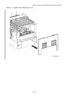 272
272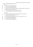 273
273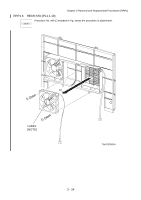 274
274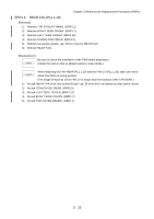 275
275 276
276 277
277

