Dell 5110cn Color Laser Printer Service Manual - Page 590
Signal line name, Description, FAN LOW, FAN STOP, FAN REAR ONH
 |
View all Dell 5110cn Color Laser Printer manuals
Add to My Manuals
Save this manual to your list of manuals |
Page 590 highlights
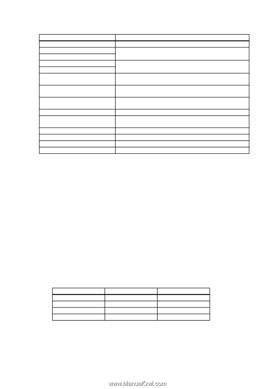
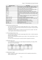
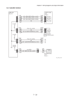
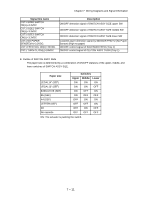
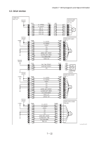
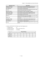
Chapter 7 Wiring Diagrams and Signal Information Signal line name 24V OSC OFF HEAT1 xHEAT1 HEAT2 xHEAT2 HEAT EN IL OPEN SLEEP xREAR FAN STOP xREAR FAN LOW ALM FAN REAR xLVPS FAN STOP LV TYPE ALM FAN LVPS Description Control signal for +24 VDC output (High: Output is stopped) Control signal of Main Lamp placed in FUSER ASSY (LAMP lights up at "High: HEAT1" and "Low:xHEAT1") Control signal of Sub Lamp placed in FUSER ASSY (LAMP lights up at "High: HEAT1" and "LowxHEAT1") Control signal for AC power supply for Main Lamp and Sub Lamp placed in FUSER ASSY (High: AC power supply is output) Signal for opening/closing INTERLOCK SWITCH (High: Switch opens) Control signal for Sleep Mode (High: Output is stopped at +24 VDC, +5 VDC and +3VDC) Control signal for REAR FAN (High: Fan rotates) Control signal for REAR FAN (High: Fan rotates at high speed/ Low: Fan rotates at low speed) Alarm signal for REAR FAN (High: Fan fails) Control signal for LVPS FAN (High: Fan rotates) Identifying signal for LVPS Alarm signal for LVPS FAN (High: Fan fails) ♦ LVPS overcurrent protection circuit This circuit stops all outputs, if the power supply voltage 24VDC, 5VDC, or 3.3VDC is shorted. The circuit is reset, when after the cause of short was removed, the power is turned off, and then on again after certain time. * Note that the 5 V power supplies for the ESS and operation panel are excluded. The 5 VDC power supplies cannot be restored since they use a fuse. ♦ LVPS overvoltage protection circuit This circuit stops all outputs, if the power supply voltage 24VDC, 5VDC, or 3.3VDC exceeds the specified voltage respectively. At this time, the operating point is 32VDC or less for 24VDC, 7VDC or less for 5VDC, or 4.4V or less for 3.3VDC. The circuit is reset, when the power is turned off, and then on again after certain time. ♦ REAR FAN output circuit For the xFAN REAR ON (H) signal, the output voltage varies depending on the status of FAN LOW signal and FAN STOP signal. FAN LOW High Low High Low FAN STOP High High Low Low LVPS FAN is controlled by FAN STOP signal only. FAN REAR ON(H) 24V 15V 0V 0V ♦ Output stop by I/L Switch Output is stopped by I/L Switch. +24VDC output from LVPS is stopped by turning off the I/L Switch connected to LVPS. 7 - 9
-
 1
1 -
2
-
3
-
4
-
5
-
6
-
7
-
8
-
9
-
10
-
11
-
12
-
13
-
14
-
15
-
16
-
17
-
18
-
19
-
20
-
21
-
22
-
23
-
24
-
25
-
26
-
27
-
28
-
29
-
30
-
31
-
32
-
33
-
34
-
35
-
36
-
37
-
38
-
39
-
40
-
41
-
42
-
43
-
44
-
45
-
46
-
47
-
48
-
49
-
50
-
51
-
52
-
53
-
54
-
55
-
56
-
57
-
58
-
59
-
60
-
61
-
62
-
63
-
64
-
65
-
66
-
67
-
68
-
69
-
70
-
71
-
72
-
73
-
74
-
75
-
76
-
77
-
78
-
79
-
80
-
81
-
82
-
83
-
84
-
85
-
86
-
87
-
88
-
89
-
90
-
91
-
92
-
93
-
94
-
95
-
96
-
97
-
98
-
99
-
100
-
101
-
102
-
103
-
104
-
105
-
106
-
107
-
108
-
109
-
110
-
111
-
112
-
113
-
114
-
115
-
116
-
117
-
118
-
119
-
120
-
121
-
122
-
123
-
124
-
125
-
126
-
127
-
128
-
129
-
130
-
131
-
132
-
133
-
134
-
135
-
136
-
137
-
138
-
139
-
140
-
141
-
142
-
143
-
144
-
145
-
146
-
147
-
148
-
149
-
150
-
151
-
152
-
153
-
154
-
155
-
156
-
157
-
158
-
159
-
160
-
161
-
162
-
163
-
164
-
165
-
166
-
167
-
168
-
169
-
170
-
171
-
172
-
173
-
174
-
175
-
176
-
177
-
178
-
179
-
180
-
181
-
182
-
183
-
184
-
185
-
186
-
187
-
188
-
189
-
190
-
191
-
192
-
193
-
194
-
195
-
196
-
197
-
198
-
199
-
200
-
201
-
202
-
203
-
204
-
205
-
206
-
207
-
208
-
209
-
210
-
211
-
212
-
213
-
214
-
215
-
216
-
217
-
218
-
219
-
220
-
221
-
222
-
223
-
224
-
225
-
226
-
227
-
228
-
229
-
230
-
231
-
232
-
233
-
234
-
235
-
236
-
237
-
238
-
239
-
240
-
241
-
242
-
243
-
244
-
245
-
246
-
247
-
248
-
249
-
250
-
251
-
252
-
253
-
254
-
255
-
256
-
257
-
258
-
259
-
260
-
261
-
262
-
263
-
264
-
265
-
266
-
267
-
268
-
269
-
270
-
271
-
272
-
273
-
274
-
275
-
276
-
277
-
278
-
279
-
280
-
281
-
282
-
283
-
284
-
285
-
286
-
287
-
288
-
289
-
290
-
291
-
292
-
293
-
294
-
295
-
296
-
297
-
298
-
299
-
300
-
301
-
302
-
303
-
304
-
305
-
306
-
307
-
308
-
309
-
310
-
311
-
312
-
313
-
314
-
315
-
316
-
317
-
318
-
319
-
320
-
321
-
322
-
323
-
324
-
325
-
326
-
327
-
328
-
329
-
330
-
331
-
332
-
333
-
334
-
335
-
336
-
337
-
338
-
339
-
340
-
341
-
342
-
343
-
344
-
345
-
346
-
347
-
348
-
349
-
350
-
351
-
352
-
353
-
354
-
355
-
356
-
357
-
358
-
359
-
360
-
361
-
362
-
363
-
364
-
365
-
366
-
367
-
368
-
369
-
370
-
371
-
372
-
373
-
374
-
375
-
376
-
377
-
378
-
379
-
380
-
381
-
382
-
383
-
384
-
385
-
386
-
387
-
388
-
389
-
390
-
391
-
392
-
393
-
394
-
395
-
396
-
397
-
398
-
399
-
400
-
401
-
402
-
403
-
404
-
405
-
406
-
407
-
408
-
409
-
410
-
411
-
412
-
413
-
414
-
415
-
416
-
417
-
418
-
419
-
420
-
421
-
422
-
423
-
424
-
425
-
426
-
427
-
428
-
429
-
430
-
431
-
432
-
433
-
434
-
435
-
436
-
437
-
438
-
439
-
440
-
441
-
442
-
443
-
444
-
445
-
446
-
447
-
448
-
449
-
450
-
451
-
452
-
453
-
454
-
455
-
456
-
457
-
458
-
459
-
460
-
461
-
462
-
463
-
464
-
465
-
466
-
467
-
468
-
469
-
470
-
471
-
472
-
473
-
474
-
475
-
476
-
477
-
478
-
479
-
480
-
481
-
482
-
483
-
484
-
485
-
486
-
487
-
488
-
489
-
490
-
491
-
492
-
493
-
494
-
495
-
496
-
497
-
498
-
499
-
500
-
501
-
502
-
503
-
504
-
505
-
506
-
507
-
508
-
509
-
510
-
511
-
512
-
513
-
514
-
515
-
516
-
517
-
518
-
519
-
520
-
521
-
522
-
523
-
524
-
525
-
526
-
527
-
528
-
529
-
530
-
531
-
532
-
533
-
534
-
535
-
536
-
537
-
538
-
539
-
540
-
541
-
542
-
543
-
544
-
545
-
546
-
547
-
548
-
549
-
550
-
551
-
552
-
553
-
554
-
555
-
556
-
557
-
558
-
559
-
560
-
561
-
562
-
563
-
564
-
565
-
566
-
567
-
568
-
569
-
570
-
571
-
572
-
573
-
574
-
575
-
576
-
577
-
578
-
579
-
580
-
581
-
582
-
583
-
584
-
 585
585 -
 586
586 -
 587
587 -
 588
588 -
 589
589 -
 590
590 -
 591
591 -
 592
592 -
 593
593 -
 594
594 -
 595
595 -
596
-
597
-
598
-
599
-
600
-
601
-
602
-
603
-
604
-
605
-
606
-
607
-
608
-
609
-
610
-
611
-
612
-
613
-
614
-
615
-
616
-
617
-
618
-
619
-
620
-
621
-
622
-
623
-
624
-
625
-
626
-
627
-
628
-
629
-
630
-
631
-
632
-
633
-
634
-
635
-
636
-
637
-
638
-
639
-
640
-
641
-
642
 |
 |