Dell Force10 S25N-S50N Installing S25N and S25V Systems - Page 10
Equipment, Installing Backup Power,
 |
View all Dell Force10 S25N-S50N manuals
Add to My Manuals
Save this manual to your list of manuals |
Page 10 highlights
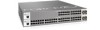
fn00158s25V Figure 2 The S25V Rear View Label (Part #, Serial #, MAC Address, Bar Code, FRU #) 10-Gigabit Modules or Stacking Modules (optional) DC Power 11.5 FG -48V RTN Current -48V Sharing 28 27 26 25 Ethernet Port Numbers 25 to 28, Right to Left Ground Connector AC Power Receptacle Figure 3 The S25N Rear View Label (Part #, Serial #, MAC Address, Bar Code, FRU #) 10-Gigabit Modules or Stacking Modules (optional) fn00158s25P 28 27 26 25 Ethernet Port Numbers 25 to 28 (numbered right to left, facing rear) Ground Connector Dual AC Power Receptacles Equipment The following items are necessary to install the system: • The switch • At least one grounded AC power source for the S25N switch (ideally two for the two AC receptacles), and one for the S25V. The S25V provides the option of using DC power with, or in addition to, AC. • Cable (included) to connect the AC power source to the switch • Brackets ("rack ears") for rack installation (included) • Screws for rack installation (included) and #2 Phillips screwdriver (not supplied) Other optional components are: • Stacking cables for connecting switches when stacked (not supplied). See Connecting Stack Ports (optional) on page 27. • Backup DC Power Module (see Chapter 4, Installing Backup Power, on page 31) • Rear rack-mounting kits (see Installing the System in a Rack or Cabinet on page 21) • Optical networking components (see Chapter 5, Installing Ports, on page 37) • Stacking components (see Ports, below) 10 System Overview
-
 1
1 -
2
-
3
-
4
-
 5
5 -
 6
6 -
 7
7 -
 8
8 -
 9
9 -
 10
10 -
 11
11 -
 12
12 -
 13
13 -
 14
14 -
 15
15 -
16
-
17
-
18
-
19
-
20
-
21
-
22
-
23
-
24
-
25
-
26
-
27
-
28
-
29
-
30
-
31
-
32
-
33
-
34
-
35
-
36
-
37
-
38
-
39
-
40
-
41
-
42
-
43
-
44
-
45
-
46
-
47
-
48
-
49
-
50
-
51
-
52
-
53
-
54
 |
 |
